How to Prevent Thin-Wall Deformation When CNC Machining Robot Joint Housings?
By JunWen Liu | Oct. 26, 2026
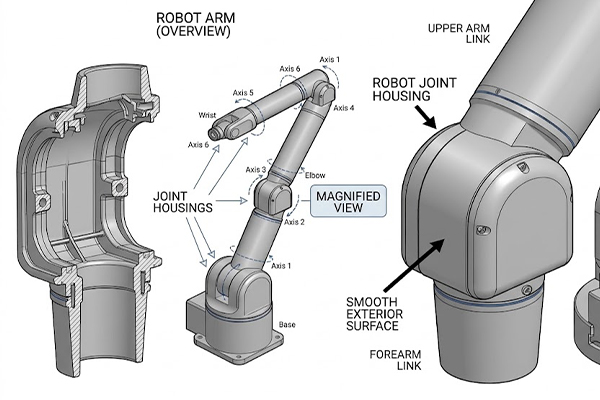
Robots such as collaborative robots, quadruped robots, and medical exoskeletons all feature a critical component: the robot joint housing. To achieve lightweight design and operational flexibility, robot joint housings are frequently designed with very thin walls (e.g., 1.0 mm to 1.5 mm). However, thin-wall robot joint housings present severe quality risks during CNC machining, including deformation, springback, and out-of-tolerance dimensions. And the deformation causes and prevention are what we will focus on today.
This article explores essential considerations and actionable guidelines for your engineering and procurement teams when designing or sourcing thin-wall robot joint housings, covering materials, design, surface treatments, and costs. At the end of the article, we will also share a case study illustrating how we helped a robotics industry client achieve 70% to 97% yield rates in thin-wall robot housings.
CNC robot joint housings typically include several key types: motor housings designed to accommodate frameless motors, reducer housings or flexspline adaptors that tightly integrate with reducers, and joint link connectors that join various articulating joints in humanoid robot.
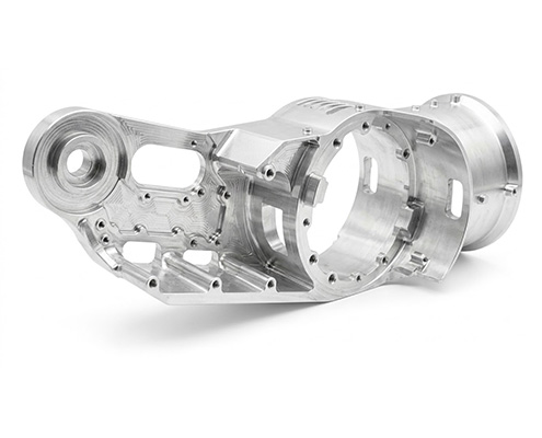
These thin-walled structures serve critical functions:
CNC machining is a manufacturing process that uses high-precision computer programming to control machine tools for multi-axis milling and cutting of metal blanks. For these thin-walled joint housings, the core benefit of CNC machining lies in its ability to achieve micron-level dimensional tolerances and high-precision concentricity control.
This not only perfectly meets the stringent requirements for precision locating references and torque fulcrums, but also significantly reduces weight while ensuring high deformation resistance and long-term stability of the thin-walled structures under complex operating conditions.
Thin-wall joint housings deform during CNC machining primarily due to the combined effects of residual stress, clamping force, and cutting force/thermal stress. This is directly linked to your choice of material, as a material’s rigidity, thermal expansion coefficient, and internal stress state dictate how easily it deforms.
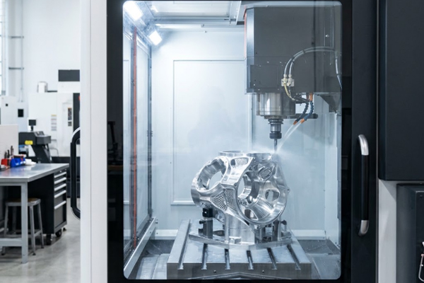
6061 and 7075 offer low density and high machinability, but feature high thermal expansion coefficients and significant internal stress.
It is often used in ultra-lightweight robotic arms (such as AZ91D). Its elastic modulus is even lower than aluminum, making it bend more easily under identical clamping and cutting forces. It also dissipates cutting heat poorly, requiring strict machining parameters.
Titanium is commonly used in high-load or medical robots (such as Ti-6Al-4V). Titanium has strong intrinsic rigidity, resulting in less stress deformation than aluminum. However, it is notoriously hard to machine, producing massive cutting forces and poor thermal conductivity, which traps heat on thin walls and causes localized thermal distortion.
They feature high rigidity and a low thermal expansion coefficient; when fully annealed, it offers the highest machining stability. However, due to its heavy weight, it is usually restricted to internal bearing seats or gear areas rather than the entire outer housing.
When a professional machine shop receives your engineering drawings for a 7075 aluminum joint housing with thin-wall deformation risks, process engineers implement a systematic “Deformation Control Workflow.”
They never complete machining in a single setup; instead, they prevent warping through step-by-step stress relief and flexible workholding strategies.
Machine Shop Deformation Control
| Workflow Phase | Specific Shop Action | Primary Problem Solved |
| Material Control | Mandate 7075-T651 stock; apply stress relief annealing if needed | Eliminates raw material residual internal stress |
| Machining | Roughing ➔ 24–48h Natural Aging ➔ Light Finish Cuts | Prevents spontaneous warping caused by rapid material removal |
| Workholding | Deploy 120° sector soft jaws, top-down clamps, or cavity wax potting | Eliminates elastic springback caused by localized clamping forces |
| Toolpaths | High-speed trochoidal milling + climb milling + symmetrical passes | Reduces cutting thrust and localized heat accumulation |
Instead of cutting down to final dimensions in one go, shops execute multi-stage machining:
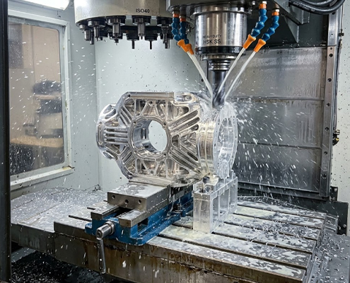
Standard three-jaw chucks crush thin walls into ellipses. For precision finishing, shops rely on specialized workholding:
When designing thin-walled robot joint housings, selecting the wall thickness requires a trade-off between weight reduction, structural rigidity (torsional and impact resistance), and CNC machinability (yield rate and production cost).
Based on manufacturing data for common engineering metals, wall thickness recommendations are categorized as follows:
1.5 mm–2.0 mm: Recommended Thickness Range
1.0 mm–1.2 mm: High-Difficulty Machining Range
Below 0.8 mm: Pure CNC Milling Not Recommended
The price variance is massive, often reaching several times the difference.
It is important to understand that for thin-walled parts, machining costs frequently far exceed raw material costs. The thinner the wall, the more machine hours, custom fixturing costs, and scrap risk a shop must account for to control deformation.
Below is a comprehensive comparison table for the four most common materials under identical ultra-thin designs (e.g., 1.5 mm wall thickness):
| Material Type | Raw Material Cost | CNC Machining Difficulty and Time | Total Combined Quote (Material + Machining) | Cost Characteristics |
| 6061-T651 Aluminum | $ Lowest | Easy, fast cutting speeds | Baseline (1x) | Low tool wear and the most mature deformation control techniques. |
| 7075-T651 Aluminum | $$ Slightly higher (~1.5x of 6061) | Moderate, high hardness and internal stress | Approx. 1.3x-1.8x | Though raw material costs slightly more, its high strength gives thin walls better rigidity during cutting than 6061. Experienced factories will not quote excessively high prices. |
| Stainless Steel (304 / 316) | $$ Moderate | Difficult (gumming, work hardening) | Approx. 2.5x-3.5x | Heavy material; rarely used for full thin-wall housings. Prone to heat-induced warping during machining, requiring tiny cut depths. Machining time is 2-3x longer than aluminum, causing high tool wear. |
| Titanium Alloy (TC4 / Gr5) | $$$$ Very expensive (5-8x of aluminum) | Very difficult (poor thermal conductivity, massive cutting forces) | Approx. 5x-8x or higher | Thin-wall part costs are exceptionally high. Must be cut at very slow speeds. The raw material is expensive, and any slip-up during machining causes scrap due to heat accumulation. This is why shops quote high premiums. |
Recommendations:
For thin-walled robot joint housings designing, incorporating Design for Manufacturing (DFM) principles early on minimizes CNC machining deformation caused by thin walls, cutting forces, and residual stresses.
Key design rules include:
Condition 1: Sliding Friction Surfaces for Oil Seals
When dynamic oil seals rotate or reciprocate against the housing journal, surfaces that are too rough cause rapid rubber wear and oil leaks, while surfaces that are too smooth prevent micro-oil film formation, leading to dry friction burn.
Preferred (Cost-Effective): 7075-T651 Aluminum + Hard Anodizing with PTFE Impregnation. Provides high hardness against dust scratches and an extremely low friction coefficient.
Advanced (Medical/Lightweight): Titanium (Ti-6Al-4V) + PVD Chrome Plating or DLC (Diamond-Like Carbon) coating.
Surface Roughness: Must be strictly controlled between Ra 0.2 – 0.4 µm.
Size Allowance: Hard anodizing penetrates ~50% inward and grows ~50% outward. Drawings must state: “All dimensions and tolerances apply after surface treatment.” Shops typically oversize/undersize the journal by 15–20 µm (per side) before treatment, then precision polish/hone back to ±0.01 mm tolerance.
Lead-in Chamfer: Design a 15°–30° smooth lead-in chamfer with rounded edges to prevent cutting the oil seal during press-fitting.
Condition 2: Gear Contact Surfaces (e.g., Circular Splines / Internal Gear Rings)
Integrating harmonic or planetary gear teeth directly into thin walls exposes them to heavy rolling and sliding shear stresses.
Critical Warning: Never machine gear teeth directly into aluminum. Even with hard anodizing, the soft aluminum core causes an “eggshell effect” under heavy loads, leading to tooth spalling and failure.
Preferred (Lightweight + Strength): 42CrMo (Quenched and Tempered + Gas Nitriding) or 17-4PH Stainless Steel (H900 Aging). Nitriding achieves a hardness of HV600–HV800 with minimal distortion.
Ultimate Solution: A 7075 aluminum outer housing + press-fitted ultra-thin steel gear ring. This pairs steel wear-resistance with aluminum weight-saving.
Distortion Control: Gas nitriding temperatures (500–550°C) can cause micron-level ovality on thin walls. Gear parameters must be specified as post-nitriding dimensions, requiring precision gear grinding to correct.
Will Machine Shops Charge Extra?
Yes, significantly. This premium precision pricing stems from three factors:
Specialized Setup and Minimum Batch Fees: Hard PTFE anodizing and gas nitriding require custom titanium hanging racks to prevent thin-wall distortion, incurring separate minimum batch/start-up fees.
Secondary Finishing (Re-clamping): To hit micron-level tolerances, the workflow becomes: Roughing ➔ Stress Relief ➔ Finishing ➔ Surface Treatment ➔ Secondary Precision Polishing/Honing. Machining hours effectively double.
Scrap Risk Premium: Thin-walled parts face high risks of acid over-etching (aluminum) or thermal stress cracking (steel) during treatment. Shops typically bake a 10%–20% scrap risk buffer into sample quotes.
Recommended Prototype Combination
To balance deformation control, surface performance, and budget during prototyping:
Use 7075-T651 Aluminum with a wall thickness of 1.5 mm – 2.0 mm for the main housing.
For Oil Seal Surfaces: Machine directly into the aluminum housing, specified as Hard Anodizing + Local Ra 0.4 Precision Polishing.
For Gear Surfaces: Avoid cutting teeth into aluminum. Purchase a standard steel gear ring (or machine an ultra-thin quenched steel ring) and press-fit (interference fit) it into the aluminum housing.
Controlling Thin-Wall Deformation in Robot Joint Housings and Achieve Yield Rates from 70% to 97%
The core technical challenge in machining thin-wall connecting housings lies in preventing elastic springback after releasing the clamps. We worked with a collaborative robot manufacturer facing a severe production bottleneck: their aluminum housings featured thin walls (0.5 mm to 2.0 mm), and the machining process used by their previous supplier resulted in a yield rate of only 70%, causing frequent bearing fitting issues during assembly.
Instead of adjusting surface cutting parameters, our engineering team analyzed the error sources across the manufacturing process and implemented four specific controls:
Avoid applying excessive clamping pressure directly to thin-wall sections. Support points were aligned with rigid internal structures to distribute clamping forces evenly across the housing.
Roughing removes the majority of the material. Clamps are then fully released to allow internal residual stresses to dissipate. A semi-finishing pass reveals any geometric springback, allowing operators to compensate before the final finishing pass.
High-precision bearing bores are machined only after the overall bearing seat geometry has stabilized. This ensures the bore positions and mounting faces remain locked within a single coordinate system.
Multi-axis CNC machining reduces part re-clamping and re-alignment, which minimizes cumulative positioning errors between features.
Results
Applying this method to a 200-piece batch produced the following changes:
For a detailed look at the core hardware requirements behind precision robotic motion, explore our technical breakdown on what is the most important part of a robot.
Preventing machining deformation in thin-walled robot joint housings requires systematic control across material selection, structural design, machining processes, and surface treatments. Through this article, I believe you have learned these key aspects:
Applying these engineering rules helps resolve springback and bearing bore out-of-tolerance issues, reducing scrap rates and overall manufacturing costs while maintaining lightweight design and mechanical performance.
Are you currently developing thin-walled robot joint housings or encountering dimensional instability or deformation in your existing production runs? Contact our engineering team today for a detailed DFM manufacturing feasibility evaluation and quote tailored to your part’s wall thickness distribution, clamping strategy, and deformation risks. [ We support 2D Drawings (PDF files), 3D Drawings (IGS/STP/STEP files)].
 WhatsApp/WeChat/Mobile:
+86-15099911516
 Tel: 86-150-9991-1516
 QQ: 939020977
 E-Mail: service@vimetal.com.cn


Why do thin-wall aluminum housings warp even when stress-relieved 7075-T651 material is used?
While 7075-T651 plate is pre-stretched to relieve raw material stress, CNC milling releases internal stresses unevenly as material is removed. If aggressive cutting feeds, excessive localized clamping, or excessive cutting heat are introduced during machining, secondary stresses will still induce deformation upon clamp release.
Is 5-axis CNC machining strictly required for thin-walled robot joint housings?
5-axis machining is not mandatory, but it significantly improves accuracy. Multi-axis machining allows complex, multi-angled features and bearing bores to be completed in a single setup, eliminating cumulative positioning errors caused by manual re-clamping across multiple 3-axis setups.
How do machine shops inspect thin-wall housings for deformation after machining?
Shops utilize Coordinate Measuring Machines (CMM) with specialized low-force touch probes or 3D optical laser scanners. Measurements are performed while the housing is completely un-clamped and in a free-state, verifying that dimensions remain within tolerance without fixture restraint.
Can hard anodizing cause dimensional changes on thin-wall bearing bores?
Yes. Hard anodizing builds layer thickness on both sides of the surface, typically 50% penetrating inward into the aluminum matrix and 50% growing outward. For tight bearing bores (e.g., ISO H7 tolerances), the machining process must pre-compensate by adjusting initial bore diameters prior to surface treatment.