Ask people in different positions, “What is the most important part of a robot?” and you will get different answers. A software specialist points to control algorithms, the “brain.” A perception engineer advocates vision sensors, the “eyes.” An electromechanical engineer insists on servo motors, the “muscles.” Systemically, they are all correct. However, from the perspective of physical realization, a different truth emerges from the perspective.
A robot’s performance ceiling, its positioning accuracy, motion repeatability, and operational lifespan, is decided by its physical hardware. Precision mechanical structures, thin-wall joint housings, and high-precision kinematic components form the ultimate foundation.
This article dives into the key mechanical components that dictate robotic performance, addresses the critical CNC machining challenges you may care about most (from controlling thin-wall deformation to managing anodizing tolerances), and reveals how precision manufacturing brings complex robotic designs to life.
Critical CNC Machined Robotics Components: Joint and Transmission Systems
What It Covers
The joint and transmission system acts as the “power center and kinematic axis” of a robot. This system primarily includes:
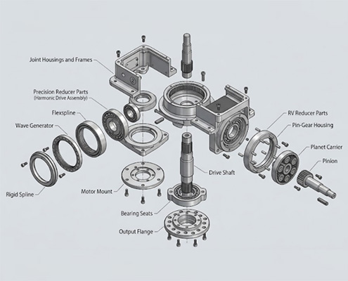
- Joint Housings andFrames: Structural enclosures engineered to protect and support gearboxes, motors, and encoders under load.
- Precision Reducer Parts: Flexspline/rigid spline housings for harmonic reducers, planet carriers, and pin-gear housings for RV reducers.
- Drive Shafts andOutput Flanges: High-rigidity rotational components connecting power sources to end actuators.
- Motor Mounts andBearing Seats: Precision bases providing axial/radial load capacity and alignment accuracy.

Key Role and Impact
As the “skeleton and muscle joints” of a robot, the machining quality of this system directly determines three performance pillars:
- Physical Accuracy:Micro-level concentricity and position tolerance of reducer housings and bearing seats dictate end-effector positioning and motion repeatability.
- Dynamic Response andRigidity: High-rigidity structures resist torsional deformation under rapid start-stops and heavy loads, preventing mechanical chatter.
- Operational Lifespan andEfficiency: Superior surface finish and geometric tolerances minimize friction and wear, optimizing energy transmission and extending service life.
Case 1: Why Do Bearing Seats produce Abnormal Noise After Assembly Even When Dimensions Pass Inspection?
A bearing bore passing dimensional checks doesn’t guarantee a quiet joint. If two bearing bores lack true coaxiality, assembly binding and noise are inevitable, much like door hinges that share accurate hole sizes but align poorly.
Thin-wall structures make this harder. A 0.8mm aluminum housing appears perfectly round while clamped on the CNC machine. Once unclamped, internal stress release causes elastic recovery, distorting the bore. Subsequent surface treatments add plating thickness, creating interference, vibration, and abnormal noise during final assembly.
To avoid noise, machining must be managed as a holistic error chain:
- Relieve Internal Stress First:Never rush into finish machining directly after roughing. Leave sufficient stock and perform vibration stress relief or cryogenic treatment to stabilize the material.
- Single Datum Strategy:Machine all critical faces and bores under a single setup and unified datum. Switching setups introduces cumulative errors that misalign the rotational axis.
- Beyond Bore Inspection: Diameter measurement alone is insufficient. Validate true position using a CMM, and conduct functional torque and acoustic testing post-assembly. Process capability is only proven when batch Cpk data stabilizes.
By implementing this methodology, we (VMT CNC Prototyping Machining Factory) helped a client elevate their humanoid knee joint assembly pass rate from 76.3% to 99.7%, while keeping noise levels stably below 41 dB.
Case 2: How We Remove Chatter Marks on Robotic Arm Joint Housings?
This is also an issue that one of our clients encountered with their previous supplier. Chatter marks on joint gear surfaces usually stem from a combination of clamping distortion, residual stress, and misaligned inspection standards:
- Align Inspection Baselines:Discrepancies between supplier and customer measurement setups can double perceived error readings. Align inspection routines strictly to the drawing’s datum face and bore centerline.
- Redesign Clamping to Prevent Deformation: For thin walls under 3mm, traditional 3-jaw chuck outer-diameter clamping causes springback upon release. Replacing this with end-face clamping and expanding collets reduced clamping deformation by over 50%.
- Rough/Finish Separation for Stress Relief:Roughing removes up to 80% of material, releasing significant internal stress. Introducing a 24-hour natural aging period between roughing and finishing allows the part to relax completely.
- Adaptive Feed Rate Control:Material allowance varies across complex gear profiles. A constant feed rate generates fluctuating cutting forces. Dynamically adjusting feed rates, slower on heavy stock, faster on light stock, virtually removes chatter marks.
For stable mass production, temperature-controlled workshops and strict tool life management are mandatory. (Note: Cutting parameters must be re-validated when transitioning between aluminum alloys and high-strength steels).
Focus 3: Sourcing Humanoid Robot Parts: A 6-Dimension Vendor Evaluation Framework
When selecting a CNC vendor for ultra-precise, thin-wall (0.8mm) robot components, usually are the humanoid robot parts, relying solely on price quotes or equipment lists is risky. We recommend using a 6-Dimension Evaluation Framework to score potential manufacturing partners:
- Technical Capabilities (25 Points): Focus on 5-axis machine ratio (>10% ideal) and minimum wall-thickness machining limits.
- Quality System (20 Points): Evaluate critical dimension Cpk tracking, CMM inspection protocols, and GDandT verification.
- Delivery Reliability (20 Points): On-time delivery rates and production capacity buffer.
- Engineering Service (15 Points): Proactive DFM (Design for Manufacturability) support during prototyping.
- Cost Structure (10 Points): Transparent pricing aligned with batch scaling.
- Scalability andRisk Control (10 Points): Material traceability and contingency planning.
Tips: Disqualify any supplier scoring below 40 points. If two vendors tie, assign a trial batch to compare sample performance. Vendor selection isn’t about finding the lowest bidder but choosing the lowest manufacturing risk.
Critical CNC Machined Robotics Thin-Wall and Structural Parts
What It Covers
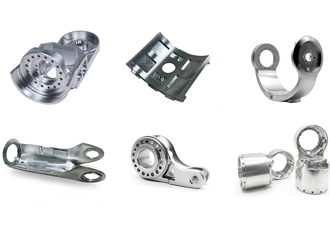
Thin-wall and structural components serve as the “skeleton and shell” of a robot. In CNC machining, these parts typically feature large spans, complex geometries, and localized ultra-thin wall sections (often between 0.5mm and 2.0mm). Key components include:
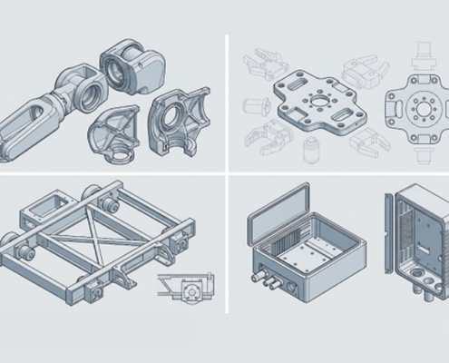
- Joint Housings andArm Links: Lightweight body structures engineered to carry the robot’s overall weight and dynamic loads.
- End-Effector Mounting Plates / Flanges:Precision interfaces designed to connect grippers, suction cups, welding torches, or sensors.
- Base Frames andChassis: Load-bearing bases that dictate overall structural rigidity and mounting surface accuracy.
- Control Box Enclosures: Thin-wall protective housings offering a balance of sealing, heat dissipation, and lightweight performance.

Key Role and Impact
- Maximizing Strength-to-Weight Ratio: Lighter structural components boost the robot’s payload-to-weight ratio and dynamic response speed while reducing motor energy consumption.
- Preventing End-Effector Cumulative Error:Even a minor 0.02mm flatness distortion on a mounting plate or arm link gets amplified over the reach of the robotic arm, resulting in millimeter-level positioning errors at the end effector (gripper/welder).
- Protecting Precision Internal Components:Joint housings act as protective barriers. If machining deformation causes poor sealing, dust and moisture intrusion can directly damage high-value internal reducers and encoders.
Case 4: Controlling Thin-Wall Deformation in Robot Joint Housings
The core technical challenge in machining thin-wall joint housings lies in preventing elastic springback after unclamping. We worked with a cobot manufacturer who faced severe production bottlenecks: their aluminum housings featured ultra-thin walls (0.5mm to 2.0mm), leading to a dismal 70% pass rate and chronic bearing tightness post-assembly.
Rather than making superficial adjustments, our engineering team analyzed the holistic manufacturing error chain:
- Distribute Clamping Pressure Uniformly:Hard clamping directly over thin-walled sections must be avoided. Support points must align with rigid structures to ensure balanced force distribution.
- Multi-Stage Machining with Stress Relief:Rough machining removes the bulk of the material. Unclamping after roughing allows internal residual stresses to relax. Semi-finishing then reveals any geometric springback, allowing operators to compensate before final cuts.
- Post-Sequence Critical Features: Machine high-precision bearing bores only after the overall housing geometry has stabilized. This guarantees that bore positions and mounting faces remain locked in a unified coordinate frame.
- Maximize 5-Axis Single-Setup Processing:Multi-axis CNC machining minimizes part re-clamping and re-alignment. Eliminating unnecessary setups directly removes cumulative positioning errors.
By implementing this systematic methodology, assembly pass rates for a 200-piece batch surged from 70% to 97%, while delivery was accelerated by five days. When evaluating CNC partners, don’t just look at machine lists, ask how they prove parts maintain form after unclamping.
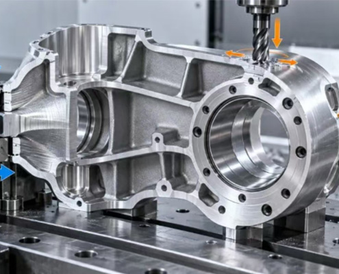
Focus 5: Preventing Flatness Springback in Robot End-Effector Mounting Plates
In precision sheet and plate machining, true expertise is measured by whether a part remains flat after releasing clamp pressure.
- Differentiate Flatness from Parallelism: A single flat surface does not guarantee proper assembly. Assembly binding often stems from non-parallel mating faces or hole position drift, not just surface flatness.
- Never Force Flatness with Excessive Clamping: Clamping is meant to hold a part, not bend it straight. Over-clamping distorts thin plates, causing immediate springback upon release and creating wave-like stress patterns.
- Symmetrical Cavity Milling andDouble-Sided Stress Relief: Deep single-sided pocketing disrupts internal stress equilibrium, warping the plate. The correct protocol requires alternating light passes on both sides, followed by unclamping, thermal cooling, and re-measuring before finish passes.
- Inspect UnderActual Assembly Conditions: Measuring a freshly machined, warm part yields vastly different results from testing a stabilized, room-temperature part. Quality protocols should specify whether parts are measured in a free-state (3-point support) or constrained under simulated bolt torque.
Vendor Evaluation Tip: Don’t be swayed by shiny machine lineups. Ask prospective manufacturing partners five direct questions: How do you establish datums? What is your material removal sequence? When do you release clamping stress? How are thin features supported? How do you inspect final geometry in a free-state? If they cannot answer these crisply, their thin-wall machining capabilities remain unproven.
Critical CNC Machined Robotics Components: Seals, Surface Finishing and QA Control
What It Covers
Sealing surfaces and housing enclosures form the protective shield of a robot, critical for maintaining high ingress protection ratings. Key components include:
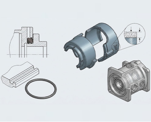
- Sealing Flanges andO-Ring Grooves: Precision machined grooves and mating faces on joint housings and motor covers.
- Anodized Structural Enclosures: Lightweight aluminum joint shells requiring protective anodized or hard-coat finishes.
- Reducer Housing Bodies: High-precision casings housing speed reducers, requiring rigorous full-process quality assurance.

Key Role and Impact
- Environmental Protection andIP Sealing: Superior surface roughness on mating faces ensures reliable sealing ring compression, preventing oil leakage or dust and water ingress in harsh industrial environments.
- Dimensional Stability Post-Finishing: Aluminum anodizing builds an oxide layer that alters critical hole diameters and thread sizes. Unaccounted anodizing buildup leads to assembly interference.
- Full-Process Traceability:Precision reducer housings demand complete process control, from raw material stress relief to coordinate measuring machine verification, to ensure process capability stability in batch production.
Case 6: Anodizing Tolerance Control: Managing Dimensional Shifts Before and After Anodizing
Anodizing aluminum robot housings carries significant dimensional risks. The oxide layer grows in both directions, consuming aluminum inward while expanding outward. As a result, internal bores shrink while external dimensions expand. For a thin anodic film, single-sided dimensions typically shrink or build by a few microns.
When evaluating CNC and surface finishing partners, focus on five non-negotiable indicators:
- Pre-Plating Offset Calculations: Capable vendors pre-calculate dimensional growth and adjust CNC toolpaths accordingly during drawing review.
- Closed-Loop Film Thickness Control: Strict regulation of bath temperature and current density maintains batch-to-batch film variance within a tight range of a few microns.
- Precision Masking Protocols: High-tolerance bearing bores and threads must be reliably masked to prevent assembly binding.
- Post-Anodizing Geometric Re-Inspection: Quality checks must extend beyond basic diameters to include flatness, roundness, and form tolerances.
- Data Transparency:Vendors must provide documented pre- and post-anodizing dimensional and film thickness reports, eliminating black-box processing.
One of our robotic clients previously separated CNC machining and anodizing across two suppliers. The resulting bore shrinkage made bearing press-fitting impossible, dropping yield rates to roughly two-thirds. After transitioning to a single vendor capable of managing the full process, pre-compensating allowances and tracking batch film thickness, assembly yield surged to nearly one hundred percent. Ultimately, precision surface finishing relies on data-driven process control.
Focus 7: Preventing Sealing Failures: Achieving True Surface Integrity Beyond Roughness
Preventing fluid leakage in robot joint sealing surfaces requires more than achieving a low surface roughness. True sealing integrity demands a holistic tolerance strategy, and our team used to adhere to the followings for our clients:
- Complete Engineering Drawings First: Never rush to prototype if drawings only specify roughness. Verify that datums, flatness, and face runout tolerances are fully defined to prevent oil leakage post-assembly.
- Lock Down Raw Material Consistency: Prototyping and mass production must utilize identical material lots. Introducing thermal stress relief after roughing prevents parts from warping during storage.
- Account for Coating Thickness Early:Processes like hard-coat anodizing add significant film thickness, directly impacting sealing ring compression ratios. Determine pre-machining allowances or masking strategies prior to production.
- Statistical Process Control in Batch Runs: Sample approval is not enough for mass production. Implement first-article inspections and in-process sampling checks, logging batch data to catch process drift immediately.
Sealing surface manufacturing isn’t just following a print. Conduct thorough Design for Manufacturability (DFM) reviews to establish clear process boundaries before cutting metal.
Focus 8: Precision Reducer Housing Machining: Full-Process Control and Quality Checkpoints
The challenge in machining harmonic or speed reducer housings lies not in having multi-axis machines, but in controlling part deformation and maintaining batch consistency. Featuring ultra-thin walls and deep cavities, these parts demand strict coaxiality control across three core pillars:
- Four-Step Stress Release Protocol: Avoid single-setup processing. Rough out the bulk material, leaving a small allowance, and allow the part to rest for several hours. Perform semi-finishing with a minimal allowance, followed by a light finish pass. While slightly slower, this process elevated production yield from seventy percent to nearly one hundred percent.
- Single-Setup Multi-Axis Execution: Machine mounting faces and bearing bores in a single multi-axis setup using custom soft jaws and vacuum chucks to prevent clamping distortion. Integrated on-machine probes automatically compensate for tool wear, locking coaxiality within a single-digit micron range.
- Data-Driven Quality Inspection: Replace random manual sampling with automated statistical checks. Key dimensions are inspected every couple of hours, triggering automatic machine stops if data drifts. Unified inspection standards across multiple manufacturing sites guarantee consistent tolerances whether producing hundreds or thousands of units.
Tips: Ask prospective CNC suppliers three questions: Do you separate roughing and finishing operations? Do you operate a climate-controlled workshop? Can you provide full coordinate measuring machine inspection reports? If a supplier cannot say yes to all three, proceed with caution.
Final Thoughts
While software algorithms define a robot’s intelligence and sensors provide environmental awareness, physical hardware determines its operational limits. A robot’s positioning accuracy, motion repeatability, load capacity, and service life are ultimately governed by the precision and rigidity of its mechanical structure, joint housings, and drive components.
In practice, high-level control algorithms cannot correct for physical flaws like joint backlash, structural flexing under load, or bearing bore misalignment. Achieving reliable performance requires managing precision manufacturing as an integrated process—balancing residual stress relief, multi-axis clamping strategies, and post-surface-treatment dimensional shifts.
Facing Hardware Bottlenecks In Your Robotics Production?
For your projects struggling with any of these manufacturing challenges, our engineering team can help:
- Assembly Binding or Abnormal Noise: Bearing seats or joint housings passing dimensional checks but causing noise, friction, or alignment issues post-assembly.
- Thin-Wall Deformation: Ultra-thin joint shells or structural parts warping, twisting, or springing back after unclamping from the CNC machine.
- Plate Flatness andParallelism Issues: End-effector plates or mounting flanges bowing after pocket milling or failing to maintain parallel mating faces.
- Anodizing andCoating Interference: Critical bore shrinkage, thread binding, or out-of-spec dimensions caused by uncompensated surface treatments.
- Sealing andFluid Leakage: Mating face surface finish (Ra) or toolpath layout causing IP-rating test failures or oil leaks under pressure.
- Batch Consistency Drops: High failure rates or wide Cpk variance when scaling joint components from prototypes to production runs.
Submit your 2D and 3D drawings for a free technical DFM review, or talk to our engineering team about solving your manufacturing challenges. [2D Drawings (PDF files), 3D Drawings (IGS/STP/STEP files)].
Frequently Asked Questions
If physical hardware dictates performance, can’t software algorithms compensate for small mechanical inaccuracies?
Software can compensate for static positioning errors through calibration matrices, but it cannot fix dynamic physical limitations. Mechanical issues like joint backlash, frame flex under load, thermal expansion, or bearing misalignment cause unpredictable micro-vibrations and hysteresis. When the physical structure lacks rigidity and precision, no control algorithm can achieve high-speed, sub-millimeter repeatability.
Is there a single robotic component that causes the highest rate of assembly failures?
Failures rarely stem from a single broken part; they usually result from cumulative tolerance stack-ups across joint assemblies. Joint housings, speed reducer interfaces, and bearing seats are the most common culprits. If the concentricity, perpendicularity, or thin-wall roundness of these components deviates even by microns, the entire kinematic chain suffers from binding, noise, and premature wear.
Why is thin-wall machining (0.5mm–2.0mm) such a critical benchmark for a robotics CNC supplier?
Modern robotics—especially humanoid and collaborative robots, demand extreme weight reduction without sacrificing structural strength. Thin-wall machining tests a vendor’s ability to control residual stress, thermal expansion, and elastic springback.
How does surface integrity affect a robot’s operational lifespan beyond visual appearance?
Surface integrity directly impacts mechanical fatigue and environmental protection. Microscopic tool marks or improper surface roughness (Ra) on dynamic sealing faces lead to lubricant leaks and moisture ingress (failing IP ratings). Furthermore, uncalibrated surface treatments like hard-coat anodizing alter critical press-fit tolerances, leading to assembly stress and shortened component lifespan.
How you verify that a machined part won’t deform after being released from the fixture?
Geometric stability must be verified in a “free-state” using advanced Coordinate Measuring Machines (CMM) and optical 3D scanners after thermal stabilization. Reliable partners perform multi-stage stress relief (thermal/cryogenic aging) during machining and validate that critical datum features retain their form tolerances without relying on clamping forces to hold them true.