What Humanoid Robot Parts Can Be CNC Machined? Component Types and Production Risk Control
By JunWen Liu | Oct. 22, 2026
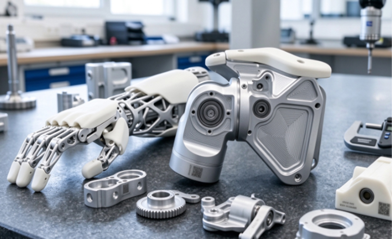

Virtually all core mechanical components in humanoid robot that require high structural strength, lightweight design, and strict physical tolerances are CNC machined. These humanoid robot components include joint actuator housings, harmonic reducer components, skeletal limb frames and chassis, precision rotation shafts, and dexterous hand mounting plates.
However, manufacturing these parts presents near-stringent engineering demands. These requirements are not monolithic:
Overview
In this article, we break down core humanoid robot component types, shape features, DFM considerations, material selection, and factory CNC machining risk control inspections one by one.
At the end of the article, we will also share a case study on how to control flatness springback in robot end-effector mounting plates. Our CNC machining factory’s dual-side material removal and staged stabilization solution successfully achieved a ±0.005mm tolerance control for a client’s dexterous hand mounting plate.
Joint actuators need to handle high torque output, severe shock loads, frequent back-drivability, and extremely constrained package sizes. These highly integrated requirements make CNC machining for this module one of the most challenging parts in overall robot hardware manufacturing.
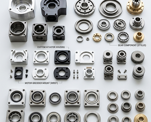
Driven by the pursuit of extreme power density and lightweight design, components in this category integrate several complex geometric features:
Tolerances for joint components are exceptionally stringent. A qualified CNC machining partner approaches these drawing requirements with targeted DFM insights and dedicated machining strategies:
The manufacturing cost of joint modules depends heavily on a supplier’s end-to-end process control:
The skeletal frames and structural connectors form the load-bearing backbone of a humanoid robot. Because a humanoid arm or leg functions as a serial kinematic chain, mechanical errors or compliance at any individual structural segment accumulate down the line. To maintain overall payload capacity, joint stiffness, and end-effector positioning accuracy, engineering teams must evaluate structural frames not as isolated brackets, but as interconnected links in a continuous kinematic series.
Structural components include upper and lower limb segments, shoulder nodes, hip connectors, thigh torque units, chassis frames, and multi-axis ankle connectors. These parts typically feature:
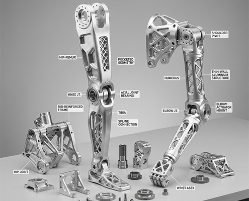
To ensure a high strength-to-weight ratio and dynamic responsiveness without sacrificing serial stiffness, material selection and geometry design should align closely:
Warping Control in Heavy Pocketing: Aggressive material removal in thin-wall structural frames releases internal residual stresses, leading to part twist or bowing. Experienced CNC shops apply balanced material removal on opposing sides, separating roughing and finishing passes to hold tight hole-position and mounting-face flatness specs.
A humanoid robot’s serial chain makes multi-interface alignment critical—a slight angular deviation on a shoulder connector translates into significant positional drift at the fingertip.
Transmission components act as vital mechanical linkages that transfer motion, torque, and force throughout humanoid robot actuators. Because smooth power transmission is essential to minimize energy loss, eliminate joint backlash, and preserve battery life, these parts demand extreme low-friction fits, tight concentricity, and superior surface finishes.
Achieving precise sliding and rotational fits (such as h6/g6 clearance limits) requires strict concentricity along the entire length of shafts and pins to prevent binding or dynamic vibration under high-speed operation.
Surface condition directly impacts friction coefficients, seal longevity, and component wear rates across millions of operational duty cycles.
Dexterous hands and sensory modules function as the primary interaction interface between a humanoid robot and its environment. Because delicate manipulation relies on micro-force tactile arrays and vision sensors, these components require exceptional dimensional stability, optical-grade surface flatness, and strict multi-axis datum alignment.
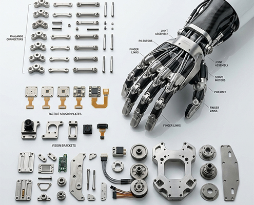
Tactile sensor arrays and optical vision modules are highly sensitive to surface irregularities. Even subtle distortion on a mounting plate introduces signal noise, localized pressure concentrations, or optical misalignment.
For depth sensors and IMUs, mechanical mounting datums dictate coordinate calibration. Any angular error at the physical mounting face directly degrades global positioning accuracy.
Achieving ±0.005mm Flatness Control in Dexterous Hand Mounting Plates
A robotic industry client approached our facility with an ongoing production bottleneck. For an ultra-thin 7075-T651 aluminum mounting plate designed for a dexterous hand tactile array, the previous supplier’s parts consistently suffered from severe flatness springback. Because the design featured deep pocketing across a 120mm x 80mm surface with a thin 1.2mm web, conventional single-sided machining and standard vise clamping caused the plates to bow significantly upon fixture release, yielding a flatness deviation exceeding 0.035mm, far outside the client’s ±0.005mm functional specification.
To solve this strict flatness control problem, our engineering team implemented a symmetrical cavity milling and dual-side stress relief protocol. Instead of cutting deep sensor pockets in a continuous single-sided pass, toolpaths were alternated symmetrically between both faces of the plate. By removing equal stock thickness from opposing sides in incremental depth steps, we maintained internal stress equilibrium within the 7075-T651 raw stock, preventing the material from twisting or bowing during initial roughing.
Following rough machining, the pre-formed plates underwent a staged stabilization period. The components were unclamped and allowed to rest in a temperature-controlled environment for 24 hours, giving residual cutting stresses sufficient time to fully dissipate in a free state. For final finishing passes, traditional mechanical clamps were replaced with a custom-engineered porous ceramic vacuum fixture. This setup distributed holding force uniformly across the entire contact plane without introducing localized clamping strain or micro-flexing.
Final metrology verification, conducted in an unclamped, tension-free state using a high-precision CMM equipped with a non-contact optical probe, confirmed that the mounting plates achieved consistent flatness and parallelism within ±0.005mm. By replacing flawed legacy processing with balanced dual-side toolpaths, intermediate stress-relief resting, and low-tension vacuum fixturing, our facility solved part springback problem, providing the client with zero-defect sensor mounting interfaces for serial production.
Scaling a humanoid robot from early-stage prototype to reliable serial production is fundamentally an exercise in error and budget control. As we have explored across joint actuators, skeletal frames, transmission elements, and sensor mounts, performance metrics like dynamic response, optical sensor alignment, and acoustic noise level are not merely algorithm problems,they are defined by micron-level concentricity, free-state flatness, and systematic residual stress control. Whether machining compact humanoid actuators or heavy-duty industrial end-effectors, partnering with an experienced shop for robotics and automation CNC machining services ensures consistent batch repeatability. Looking to scale your next-generation hardware from prototype to production? Explore our comprehensive custom robotics CNC machining solutions to lower your manufacturing risk. [ We support 2D Drawings (PDF files), 3D Drawings (IGS/STP/STEP files)].
 WhatsApp/WeChat/Mobile:
+86-15099911516
 Tel: 86-150-9991-1516
 QQ: 939020977
 E-Mail: service@vimetal.com.cn


What are the most critical materials used for CNC machining humanoid robot parts?
Humanoid robot manufacturing relies primarily on 7075-T651 and 6061-T6 aluminum alloys for high strength-to-weight ratios, Ti-6Al-4V titanium alloy for high-load structural nodes, 17-4PH stainless steel for drive shafts, and self-lubricating engineering plastics like PEEK and Delrin (POM) for low-friction bushings. Selecting the right material directly impacts joint stiffness and payload capacity.
How do you prevent thin-wall deformation during the machining of robot joint housings?
Controlling thin-wall deformation requires a multi-stage approach: separating roughing and finishing passes, allowing a 24-hour stress-relief stabilization period, utilizing custom soft jaws or vacuum fixtures to distribute clamping pressure evenly, and maintaining a unified datum across all operations.
How do you prevent bearing bore misalignment and thin-wall deformation in robot joint housings?
Thin-walled joint housings are prone to elastic springback once released from clamping fixtures, causing bearing bores to lose true coaxiality and leading to abnormal noise, binding, or premature wear during final assembly. To control this deformation, advanced manufacturing workflows avoid hard outer-diameter clamping. Instead, they utilize uniform soft-jaw or vacuum clamping, separate roughing from finishing to release internal stress, provide a 24-hour material stabilization period, and machine critical bearing bores in a single multi-axis setup to lock in precise coaxial alignment.
Why are strict roundness and total runout controls critical for robotic transmission shafts?
In high-speed humanoid robot actuators, drive shafts, pins, and spindles transfer continuous torque and rotational force. Poor roundness or excessive radial runout creates dynamic micro-vibrations, uneven bearing preloads, and excessive thermal expansion under high RPMs. Maintaining tight cylindrical tolerances (such as h6/g6 limits) and keeping runout within a few microns requires specialized Swiss-type turn-mill capabilities followed by high-precision cylindrical grinding to correct thermal distortion after heat treatment.
How do hole position precision and mating surface flatness impact robotic sub-assembly integrity?
Hole position drift (true position errors) and uneven mating surfaces prevent proper alignment between modular joint frames, gearboxes, and sensor mounting plates. Even a minor positional error or microscopic surface distortion gets amplified across the robot’s kinematic chain, resulting in cumulative end-effector positioning errors or localized stress concentrations under heavy load. Ensuring true-position hole accuracy and optical-grade flatness on mating planes requires multi-axis indexing to eliminate setup stack-ups, verified via non-contact CMM inspection in an unclamped free state.