Aluminum vs. Titanium for Humanoid Robot Joint Components: Selection Guide & Manufacturing Insights
By JunWen Liu | Oct. 30, 2026
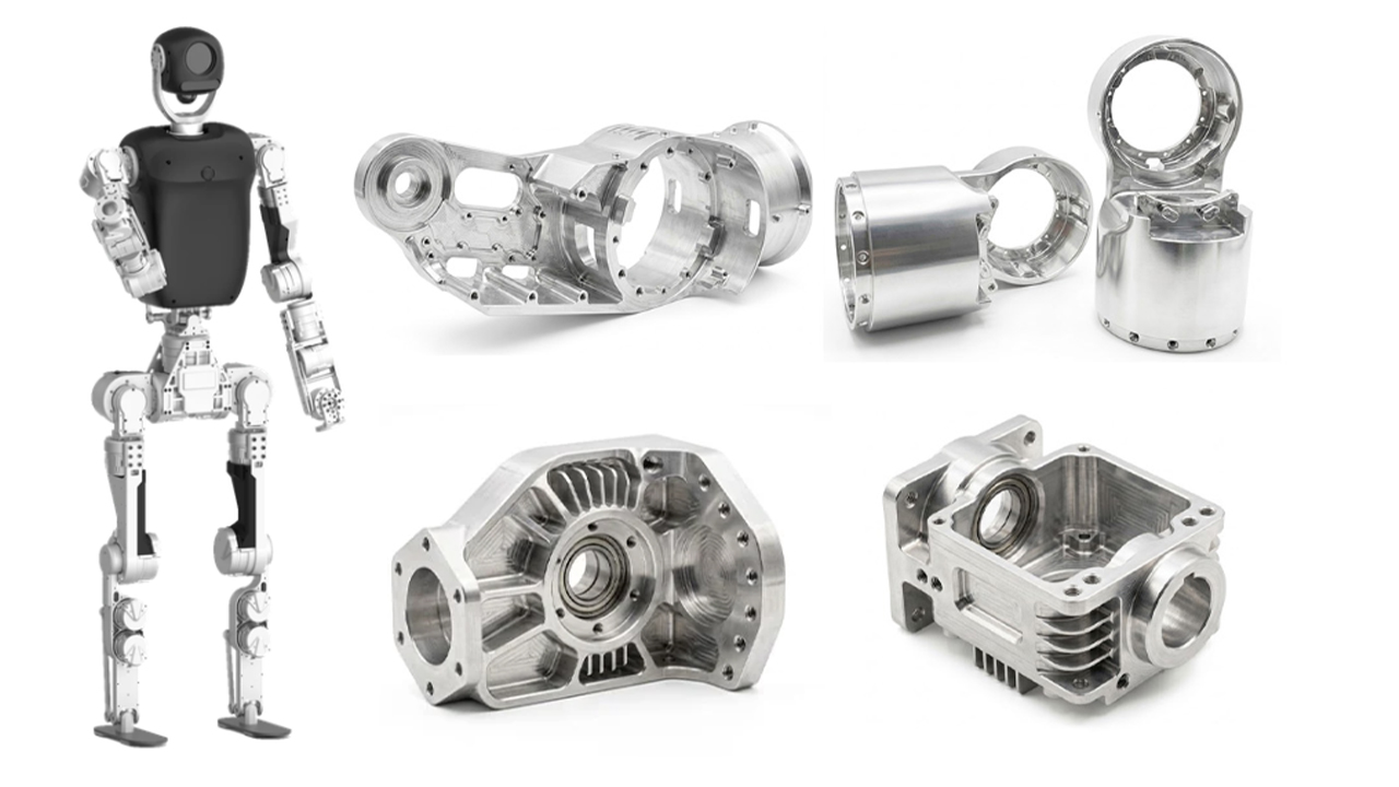

A balance should be struck among lightweighting, high strength, cost, and manufacturing feasibility when in the design and production of humanoid robot joint components. Aluminum and titanium alloys are currently the two most widely used lightweight and high-strength metals, yet their performance differs across various load ranges and joint structures. This article provides an in-depth look at their application scenarios, selection strategies, and surface treatments in custom humanoid robot joints. It also covers key design strategies for CNC-machined joint components, addressing common challenges such as deformation, galling, residual stress relief, thin-wall chatter, and machinability, for your design reference, alongside factory machining strategies to help you evaluate what to look for when selecting a manufacturing partner.
At the end, we share a case study: to address the issues of deformation and oil leakage during the machining of titanium alloy dynamic sealing drive shafts for humanoid robots, we utilized pneumatic flexible fixturing, post-roughing stress-relief annealing, and a composite cylindrical grinding process, controlling coaxiality within 0.008 mm and achieving a surface roughness of Ra 0.4 um to ensure stable delivery with zero leakage over 48 hours of continuous operation.
First, you need to understand that humanoid robot joint components encompass a wide range of parts, including hips, knees, ankles, and dexterous hands, as well as configured components such as wrist guards, dynamic sealing drive shafts, linkages, and joint output journals. Most of these parts demand high structural strength, high space utilization, and lightweighting.
Therefore, two materials are highly favored in engineering: aluminum alloys, which are lightweight, offer good strength, moderate corrosion resistance, and excellent machinability; and titanium alloys, which are lightweight, stronger, more rigid, exceptionally corrosion-resistant, but also more expensive. These two represent the most popular metal materials for precision-customized humanoid robot joints. To learn more about the detailed characteristics and grades of aluminum, you can refer to the Aluminum Grades Comparison Guide; for titanium, please refer to the Titanium Metal Grades Guide.
Additionally, customizing humanoid robot joint components often involves complex 3D geometries and micron-level mating tolerances. These can be achieved through CNC machining or 3D printing. While CNC machining delivers higher precision (±0.005 mm) and preserves the material’s inherent rigidity, 3D printing helps save raw material costs when using expensive metals like titanium. You can check out What Humanoid Robot Parts Can Be CNC Machined? to further explore other humanoid robot parts suitable for CNC machining and understand the critical importance of CNC machining in this field.
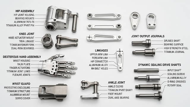
During the material selection process for humanoid robot joints, you need to systematically weigh weight, mechanical strength, raw material costs, and manufacturing process complexity. Depending on structural positions and load requirements, aluminum and titanium alloys offer distinct engineering values.
For regions demanding exceptional rigidity and fatigue strength, titanium alloys (such as Ti-6Al-4V / Grade 5) are indispensable. They are primarily utilized in hip joints, knee joints, primary drive gear assemblies, and high-impact connectors, effectively suppressing elastic deformation under heavy loads to ensure structural dimensional accuracy. However, titanium alloys suffer from low thermal conductivity, concentrating cutting heat at the tool tip and leading to rapid tool wear. Both raw material and CNC machining costs for titanium are exceptionally high.
In contrast, aluminum alloys (such as 7075-T6 or 6061-T6) dominate applications in large-area structural supports, motor housings, and skeletal brackets. Their core advantages lie in high thermal conductivity (critical for motor heat dissipation) and low material density, making them ideal for upper structural beams such as thighs and calves to achieve overall lightweighting. On the manufacturing front, aluminum parts can be efficiently and cost-effectively produced via CNC machining or high-volume die-casting. Although aluminum’s higher plasticity requires optimized tool flute designs to prevent chip adhesion, its overall machining efficiency and cost-effectiveness far surpass those of titanium.
Mapping specific material grades precisely to various joint components of a humanoid robot is closely related to the peak torque and load ranges of these parts. The table below outlines the recommended joint components, core load types, optimal aluminum/titanium grades, and cutting-edge alternative materials across different joint load levels for your reference:
| Joint Load Level (Torque Range) | Corresponding Joints and Specific Components | Core Load Type | Optimal Aluminum Grade (Condition) | Optimal Titanium Grade (Condition) | Alternative Materials |
| Ultra-High Load
> 250 N·m | Joint Output Main Shaft / Journal | Extremely high torsion, bending, impact shear | Aluminum not recommended | Grade 23 (ELI) (High toughness and impact resistance) | 4140 Alloy Steel (Excellent load capacity, but extremely heavy) |
| Integrated Thigh / Calf Main Skeleton | Axial compressive stress, long cantilever bending | 2195 / 2099 (Aluminum-lithium alloy, high stiffness for weight reduction) | Grade 5 (Supports 3D printed topology optimization) | Carbon Fiber Prepreg Tube | |
| High Load
80 – 250 N·m | High Reduction Ratio Gearbox Housing | Tension / radial expansion caused by gear reaction force | 7055-T77 (Crack-resistant high-strength aluminum) | Grade 5 (Achieves ultra-small outer diameter design) | Zinc-Aluminum Alloy (ZA-27) |
| Joint Dynamic Sealing Drive Shaft / Linkage | Medium-to-high frequency alternating torsion | 2024-T4 (Aerospace-grade high fatigue resistance) | Grade 9 (Ti-3-2.5) (Preferred for hollow thin-walled tubes) | — | |
| Medium Load
20 – 80 N·m | Integrated Framed Motor Housing | Torque reaction, motor heating (thermal stress) | 6061-T6 (CNC machined) ADC12 (Mass production die-cast) | Not recommended (Thermal conductivity too low, easily causes motor overheating) | Magnesium Alloy AZ91D (Lighter, but requires protective treatment) |
| Low / Micro Load
< 20 N·m | Dexterous Hand Micro-Linkages / Skeleton | Micro-bending, high-frequency micromotion | 7075-T6 (Utilizes high strength to support ultra-thin 0.5mm walls) | Not recommended | PEEK / Carbon Fiber Composite Plastic |
| Wrist Protective Cover / Housing / Bracket | Minor impacts, no static heavy load | 5052-H32 (Easy to bend / sheet metal component) | Not recommended | ABS / PC 3D Printed Plastic | |
| Joint Load Level (Torque Range) | Corresponding Joints and Specific Components | Core Load Type | Optimal Aluminum Grade (Condition) | Optimal Titanium Grade (Condition) | Alternative / Cutting-Edge Materials |
In addition to the aforementioned recommended materials and supported process references, hybrid manufacturing methods can also be considered. For instance, during the prototyping stage of robot joint parts, it is recommended to prioritize aluminum alloys (such as 6061/7075) for rapid machining and structural iteration to lower trial-and-error costs.
Upon entering the mass production stage, you can balance costs and performance based on the actual load bottlenecks of each joint. This may involve gradually introducing titanium alloys (such as adopting a “3D printing + CNC finish machining” hybrid process) or composite materials, or opting for direct CNC-machined titanium to achieve optimal rigidity and precision.
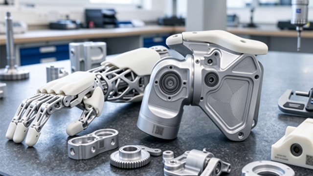
During the operation of humanoid robots, joint components are susceptible to high-frequency alternating loads and thermal deformation. Therefore, stiffness and deformation resistance are key evaluation indicators during material selection. For different stress-bearing zones, titanium and aluminum alloys exhibit distinct application strategies in deformation-prevention design:
For core transmission and stress cavities that directly bear reducers, bearings, and ball screws, areas that must withstand high torque and maintain extremely high positional accuracy, titanium alloys effectively suppress elastic deformation and prevent shifts in gear center distance thanks to their exceptional elastic modulus (high stiffness). However, material properties alone are not enough to prevent deformation; factory execution is equally critical: the fit between the bearing outer ring and the titanium hole must undergo strict thermal-mechanical co-simulation, and temperature rise tolerances must be precisely accounted for in CNC programming.
Choosing aluminum alloys for large-span linkages, robotic arm housings, and integrated motor thermal housings is essential for two main reasons: cost-effectiveness and exceptional thermal conductivity, which effectively reduces the overall temperature rise of motors during continuous high-load operations.
However, aluminum has lower stiffness than titanium, meaning it is inherently more prone to deformation than the aforementioned titanium joint components. You can compensate for lower stiffness and suppress elastic deformation by locally increasing wall thickness or designing hollow box-like structures. For detailed prevention methods regarding machining deformation in thin-walled aluminum cavity robot joints, you can refer to the Robot Joint Housing Thin Wall Deformation Guide for specific guidance.
During the mechanical assembly of humanoid robot joints, both aluminum and titanium alloy parts carry a high risk of galling (also known as cold welding or adhesive wear) under compressive friction. To prevent surface metal adhesion and seizure caused by interference fits or fretting wear, design engineers must comprehensively intervene across three dimensions: tolerance matching, counterface material selection, and surface modification treatment.
Because the passive film on titanium alloy surfaces easily flakes off under friction, leading to direct metal-to-metal contact, the core of anti-galling design lies in isolation and modification:
Aluminum alloys are relatively soft and highly ductile, making their surfaces prone to “scoring” and chip accumulation during high-interference press-fitting, which can lead to seizure:
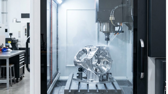
During the CNC machining of humanoid robot joints, whether choosing aluminum or titanium alloys, you will face issues beyond the overall deformation and assembly issues mentioned previously: residual stress release, thin-wall chatter, and machinability are critical factors that determine the success or failure.
Residual Stress Release
There is an aluminum alloy thigh skeleton with a thickness of 1.5 mm and a complex internal hollow structure, and the drawing specifies a bearing hole roundness tolerance of 0.01 mm. The machine shop machines it strictly according to your drawing, and machine measurements show it is fully compliant. Therefore, when choosing a manufacturing partner, you should select experienced, knowledgeable shops—those that specify measures such as “performing stress-relief aging treatment after rough machining” or advise you to add reinforcing ribs in weak, deformation-prone areas to lock in and stabilize the stress.
Thin-Wall Chatter
For example, a joint housing’s wall thickness is designed at 1.0 mm to pursue lightweighting, the CNC cutting tool may trigger high-frequency resonance the moment it touches this thin wall on aluminum or titanium sheets.
Chatter causes the inner surface of the machined bearing hole to be covered with micro-wave patterns (resulting in extremely poor surface roughness). These wave patterns prevent the bearing outer ring from fitting tightly against the hole. After the robot operates a few times, these micro-waves are flattened out, causing the bearing hole to expand and loosen. This introduces mechanical backlash in the joint and severely degrades positioning accuracy.
Therefore, it is recommended that when designing high-rigidity aluminum or titanium humanoid joints, you incorporate stepped wall thicknesses, wavy exterior profiles, or embedded honeycomb ribs. These geometric shapes disrupt resonance frequencies during the design phase, allowing the machine shop to successfully machine high-finish holes and thereby improve manufacturing yield rates.
Machinability (Tool Wear and Efficiency)
Titanium alloys are extremely difficult to machine, particularly regarding inner right angles (R-corners) and deep-hole tapping. The typical example is that an internal right angle of R0.5mm or an M2 fine-threaded hole with a depth-to-diameter ratio greater than 3 inside a titanium joint, the taps and miniature milling cutters will very likely snap directly inside the part. Once broken inside, this half-machined, expensive titanium joint is instantly ruined. Machine shops generally will not accept such designs and will advise you to modify the drawings.
Precision CNC Machining Of a Grade 5 Titanium Humanoid Robot Joint Dynamic Sealing Drive Shaft And Controll Coaxiality Within 0.008 Mm And Achieve a Surface Roughness Of Ra 0.4 Um To Ensure Stable Delivery With Zero Leakage.
In humanoid robot joint assemblies, the dynamic sealing drive shaft serves as a critical power transmission and sealing junction. Below is a realistic high-precision manufacturing case study that we recently successfully resolved for a quadruped robot client:
Core Technical Specifications:
Before partnering with us, the client assigned this order to two traditional machine shops, but prototype trials failed completely due to the following issues:
Root Cause Analysis: The previous supplier used excessive clamping force during slender titanium shaft turning, causing elastic deformation. In addition, improper cutting parameters triggered micro-chatter, and the omission of intermediate stress-relief annealing caused the parts to warp as residual stresses released over time.
To address these pain points, our engineering team redesigned the entire manufacturing workflow:
Following our process restructuring, this batch of joint dynamic sealing drive shafts successfully passed the client’s rigorous bench tests on the first run, with all core metrics meeting or exceeding drawing specifications:
Designing and producing titanium vs. aluminum humanoid robot joint components requires you to balance engineering performance with manufacturing feasibility. It also demands an understanding that their optimal application depends entirely on the specific joint location, structural geometry, and operational load profile. This article has provided specific guidance on selection scenarios for these materials. Beyond material selection, achieving micron-level mating accuracy and long-term durability for titanium vs. aluminum humanoid robot joint components hinges on rigorous DFM and specialized CNC production protocols. Mitigating key risks, such as post-machining residual stress warpage, thin-wall chatter, tool breakage in complex geometries, and surface galling during assembly—requires close collaboration between your team and an experienced precision manufacturing partner. By integrating DFM principles (such as unified datum features, anti-chatter geometries, stress-relief annealing, and advanced surface modifications like DLC/PVD or Hard Anodizing) with advanced manufacturing methods, you can successfully transition complex humanoid robot joint designs from prototype validation to high-yield, reliable mass production.
Facing challenges with titanium and aluminum grade selection, prototype manufacturing process choices, deformation, assembly, or excessive costs for your humanoid robot joint components? Contact our engineering team today for a free DFM drawing review and tailored production solutions! [ We support 2D Drawings (PDF files), 3D Drawings (IGS/STP/STEP files)].
 WhatsApp/WeChat/Mobile:
+86-15099911516
 Tel: 86-150-9991-1516
 QQ: 939020977
 E-Mail: service@vimetal.com.cn


Q1: What are the advantages of aluminum in motor thermal housings, and what are the limitations of titanium for it?
A: Aluminum possess extremely high thermal conductivity (approximately 10 times higher than that of titanium alloys), allowing them to rapidly conduct and dissipate the heat generated by motors during continuous high-load operation, thereby effectively reducing overall temperature rise. In contrast, titanium have very low thermal conductivity and severe heat accumulation. Encasing a motor directly in a titanium housing can trap internal heat, leading to motor demagnetization or efficiency degradation. Therefore, aluminum alloy is an irreplaceable material for large-span linkages or thermal housings.
Q2: What are the differences between common surface treatments used for humanoid robot joints (such as hard anodizing vs. DLC/PVD)?
A:
Q3: From the specific strength, how are the selection boundaries defined between 7075 AL and Grade 5 TI for joints?
A:
Q4: Under long-term high-frequency alternating operating conditions, what types of fretting wear are aluminum and titanium respectively prone to?
A:
Q5: For robot joints with complex structures, what advanced hybrid manufacturing routes exist in the industry?
A: For extremely high-difficulty joints with complex internal honeycomb structures that traditional multi-axis CNC tools cannot fully reach, the industry frequently adopts a “Metal 3D Printing (SLM Powder Bed Fusion) + CNC Finishing” hybrid route. Complex internal channels or lightweight lattice structures are rapidly formed via additive manufacturing first, followed by high-precision CNC turning/milling on critical bearing and sealing seats, balancing design freedom with dimensional accuracy.
Q6: When transitioning humanoid robot joints from prototypes to mass CNC manufacturing, what are the core DFM guidelines?
A: