Lightweight Robot Pocket Milling Guide: Pocket Types, Strategies, Materials, and Practical DFM Rules
By JunWen Liu | Oct. 24, 2026
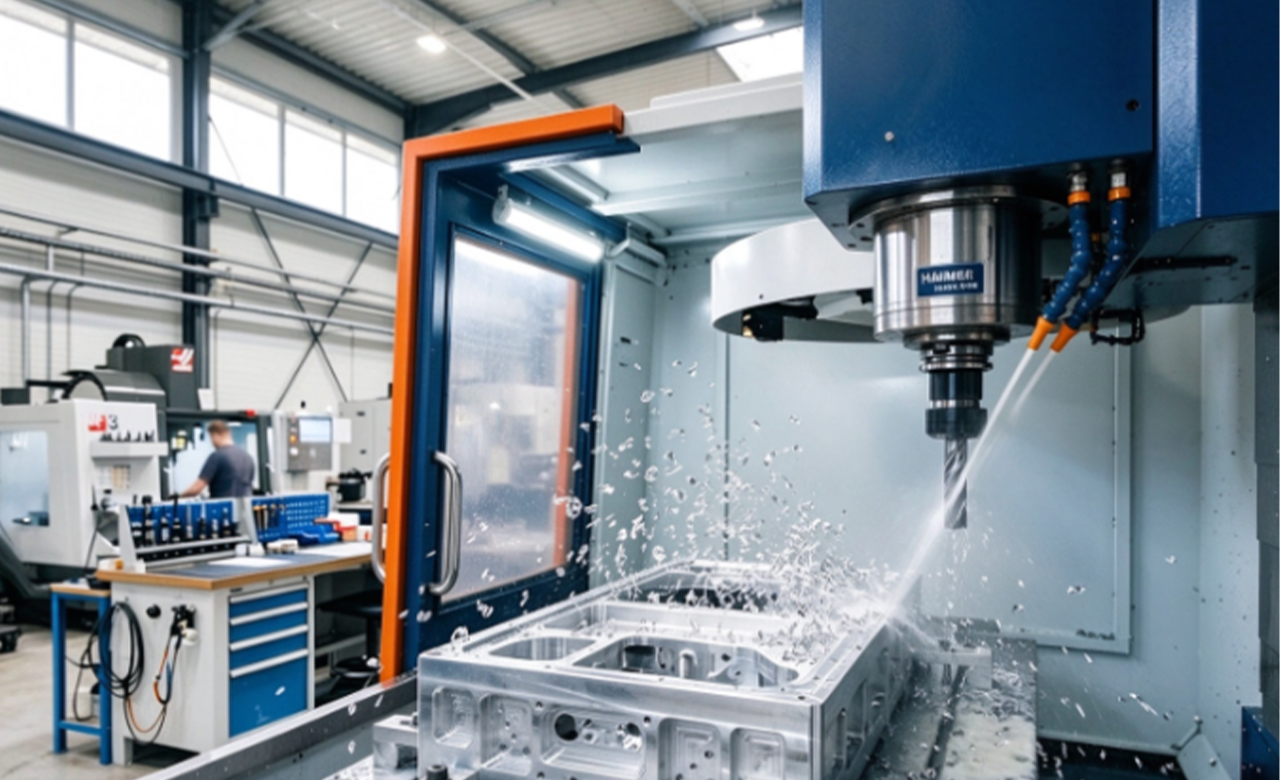

Robotic components like arm joints, chassis frames, and end-effectors require extreme lightweighting without sacrificing structural rigidity. Pocket milling, a specialized CNC machining process that removes interior material while leaving outer walls and functional ribbing intact, is the premier solution for producing these parts across three main geometries: Closed Pockets, Open Pockets, and Island Pockets.
In this guide, we dive straight into why pocket milling is essential for lightweight robotics, detailing the structural features and machining characteristics of each pocket type. You will also get actionable material recommendations (such as 7075-T6 aluminum), universal DFM (Design for Manufacturability) rules to lower cutting costs, and practical solutions to common shop-floor defects like chatter marks and fluid leaks.
Finally, we share a case study where our engineering team optimized a 7075-T6 aluminum quick-change flange joint, eliminating micro-leaks by achieving 0.01mm flatness, a Ra 0.8 µm surface finish, and a 28% reduction in cycle time.
What is Pocket Milling?
Pocket milling is a precision CNC machining process where material is selectively removed from the interior of a workpiece to create a recessed cavity, pocket, or hollow feature, leaving surrounding walls, floors, and critical structural ribs intact.
Key Advantages
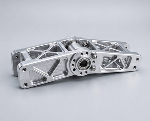
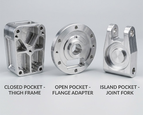
Pocket geometries of robotic hardware design vary based on structural loads, internal component routing, and assembly requirements. Understanding which robotic components are best suited for closed pockets, open pockets, and island pockets helps you learn or optimize part designs for lightweight performance. Below are these three common pocket types and their typical robotic applications, along with how each shaped component is typically machined via pocket milling for you understanding:
Advanced Computer-Aided Manufacturing (CAM) toolpath strategies can optimize part quality, shortens production lead times, and lowers unit manufacturing costs for robotic lightweight pocket components. Here is how high-efficiency and high-quality pocket milling is achieved:
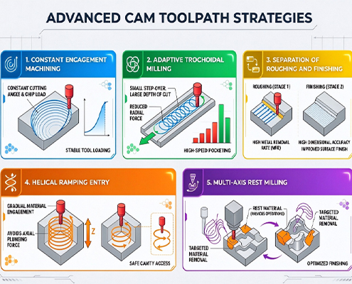
1.High-Efficiency Machining (HEM) / Dynamic Milling
Technology: Maintains a constant Cutter Engagement Angle (CEA) and uniform chip load throughout the pocket path, allowing for higher axial depth of cut (AdoC) at elevated cutting speeds.
Benefits: Shorter lead times and lower costs. Reduces roughing cycle time by 30% to 50%, minimizing expensive machine-hour expenses and accelerating delivery schedules.
2.Adaptive Trochoidal Milling
Technology: Employs smooth circular or spiral movements when machining deep or narrow slots to prevent tool burying and tool adhesion during rapid material removal in corners.
Benefits: Reduced tool wear and higher quality. Prevents sudden tool breakage, ensures stable cutting forces, and lowers scrap rates on high-value parts such as aluminum alloys or titanium alloys.
3.Strict Separation of Roughing and Finishing Operations
Technology: Bulk material is removed during heavy roughing, followed by a dedicated stress-relief dwell period. High-speed finishing passes then remove the small remaining stock allowance (such as 0.1 mm to 0.2 mm).
Benefits: Superior dimensional stability. Releases internal residual stresses in thin-walled cavities, preventing long-term part deformation and guaranteeing strict geometric tolerances during assembly.
4.Helical and Ramping Corner Entry
Technology: Instead of plunging directly into closed pockets, the end mill spirals down smoothly along a low-angle (2° to 5°) helical arc or ramp profile.
Benefits: Flawless bottom surface quality. Eliminates tool plunge chatter and dwell marks on the pocket floor.
5.Multi-Axis Rest Milling
Technology: Uses carbide tools of progressively smaller diameters to automatically detect and clear residual unmachined material in tight internal radii and narrow corners.
Benefits: Maximum weight reduction for robotic pocket parts. Enables dynamic corner weight-reduction design without requiring manual bench grinding or secondary electrical discharge machining (EDM) processes, saving downstream post-processing costs.
Comprehensive design reviews and DFM (Design for Manufacturability) analysis optimize part details specifically for pocket milling. This achieves a triple optimization of weight reduction, machining efficiency, and manufacturing cost control.
Key DFM Design Recommendations:
Internal Corner Radii
Avoid sharp 90-degree internal vertical corners, as cutting sharp corners requires small-diameter tooling, slow feed rates, or secondary EDM processes. Designing generous internal radii (R should be at least 1/3 to 1/2 of the tool diameter, or slightly larger than the cutter radius) allows the end mill to maintain continuous, high-speed circular interpolation without dwelling in corners. This prevents localized tool chatter, reduces cutting force spikes, and extends tool life.
Wall Thickness and Floor Proportions
Maintain stable minimum wall and floor thicknesses across the pocket. Thin, unsupported side walls under 1.5 mm to 2.0 mm are prone to vibration and thermal deflection during high-speed cutting, which degrades dimensional accuracy. When aggressive weight removal is required, integrating internal cross-ribbing or web structures preserves structural stiffness without adding excessive mass, ensuring the part resists deflection under cutting pressure.
Pocket Depth-to-Width Ratio
Keep pocket depths within practical tool length-to-diameter limits (L/D ratio of 4:1 or lower). As the pocket depth increases relative to tool diameter, longer tools must be used. Excessive tool overhang increases tool deflection exponentially, leading to side-wall taper, poor surface finishes, and potential tool chatter. For deeper cavities, stepping down the pocket width or adding internal ledges helps maintain tool rigidity.
Aluminum Alloys (7075-T6 / 6061-T6)
Aluminum alloys represent the industry standard for lightweight robotic structures due to high machinability and excellent strength-to-weight ratios.
6061-T6 offers outstanding corrosion resistance, excellent weldability, and lower raw material cost, making it ideal for standard structural housings, brackets, and general chassis components.
7075-T6 provides yield strength comparable to many structural steels with only one-third of the weight. It is the premier choice for high-load structural components, highly stressed arm joints, and terminal quick-change flanges where maximum yield strength and fatigue resistance are critical.
Titanium Alloys (Ti-6Al-4V / Grade 5)
Titanium grade 5 provides exceptional strength-to-weight performance, high temperature tolerance, and superior corrosion resistance. It is used in specialized high-end robotics, heavy-load joint shafts, or harsh industrial environments. However, titanium exhibits low thermal conductivity and a low modulus of elasticity, which traps heat at the cutting edge and causes material spring-back. Machining titanium requires reduced cutting speeds, specialized tool coatings, and high-pressure coolant, leading to higher tool wear and elevated machining costs compared to aluminum.
Engineering Plastics (PEEK / POM / Delrin)
High-performance engineering plastics provide extreme weight savings, electrical insulation, and low friction characteristics.
POM (Delrin) offers excellent machinability, dimensional stability, and low cost, making it suitable for lightweight covers, internal wire guides, and secondary structural components.
PEEK provides mechanical strength and heat resistance approaching that of soft metals, suited for high-temperature joint insulators or ultra-lightweight sensor housings. While raw material costs for high-grade polymers can be elevated, faster machining speeds and zero need for post-processing surface treatments help balance total production costs.
Improper cutting parameters or tooling setups can introduce surface defects and dimensional errors. Below are common machining defects encountered in robotic pocket milling and the solutions (how we solved for clients’ custom parts):
| Defect | Causes | Technical Solutions |
| Chatter Marks and Wall Vibration | • Long tool overhangs required for thin walls and deep pockets • Tool deflection and harmonic resonance under heavy cutting loads | • Implement Dynamic Milling toolpaths to maintain constant radial chip loads • Use variable-pitch and variable-helix carbide end mills to disrupt harmonic frequencies • Optimize spindle speeds and feed rates to eliminate resonance |
| Poor Surface Finish on Floors and Walls | • Poor chip evacuation leading to chip recutting and surface scoring • Incorrect feed per tooth or worn cutting edges | • Enforce strict separation between roughing and finishing operations • Apply high-pressure through-tool coolant or directed high-volume air blasts for chip flushing • Use ultra-polished or DLC-coated carbide tools for finishing passes (achieving Ra 0.8 µm or better) |
| Dimensional Inaccuracy and Wall Taper | • Heat accumulation during aggressive roughing causing thermal expansion in thin walls • Excessive radial cutting forces leading to tool deflection (tool push-off) | • Perform precision machining in temperature-controlled CNC environments • Introduce stress-relief dwell periods after roughing to stabilize temperature and stress • Utilize optical tool setters for real-time tool wear monitoring and dynamic CNC compensation |
How We Optimized a 7075-T6 Aluminum Quick-Change Flange Joint, Eliminating Micro-Leaks by Achieving 0.01mm Flatness, a Ra 0.8 µm Surface Finish, and a 28% Reduction in Cycle Time.
Background
A client developing high-payload robotic arms required custom manufacturing for a terminal quick-change flange joint made from 7075-T6 aluminum. To preserve critical mounting hole locations while achieving aggressive weight reduction, the part featured a combination of open pockets and island pockets. It exhibited classic high-precision characteristics, including thin walls (just 2 mm thick) and multiple hollow cavities.
Through detailed discussions with the client, we learned that their previous supplier’s components suffered from two major quality failures:
Upon final assembly, these defects prevented the flange faces from mating perfectly, leading to micro-leaks of air and oil that failed pressure validation.
Causes
Based on our extensive experience in precision pocket milling, we analyzed the defects and inferred that the previous supplier likely made two key process errors:
Professional Manufacturing Solutions
For this 7075-T6 aluminum flange joint project, we implemented a controlled, multi-stage machining process:
Results
Pocket milling is an essential manufacturing process for achieving the delicate balance between lightweight design and structural rigidity required in modern robotics. Throughout this guide, we explored how mastering pocket types (closed, open, and island pockets), deploying advanced CAM toolpath strategies, and following rigorous DFM design rules can drastically improve part performance. We also examined the impact of material selection, such as high-strength 7075-T6 aluminum, and how professional manufacturing techniques successfully solve common defects like chatter marks, work hardening, and assembly leaks. Need to overcome complex thin-wall challenges, reduce component weight, enhance dynamic response, and lower total production costs ? Our engineering team is here to help, and contact us today for a free DFM review and project quotation to bring precision, reliability, and cost-efficiency to your next robotic hardware build. [ We support 2D Drawings (PDF files), 3D Drawings (IGS/STP/STEP files)].
 WhatsApp/WeChat/Mobile:
+86-15099911516
 Tel: 86-150-9991-1516
 QQ: 939020977
 E-Mail: service@vimetal.com.cn