Press Fit: A Complete Guide to Interference Fit in Precision Manufacturing
By JunWen Liu | Jun. 10, 2026

A press fit holds two parts together without fasteners, adhesives, or welds. The holding force comes from one thing: controlled interference between the mating diameters. The principle is simple: the shaft is machined slightly larger than the hole. When forced together, the elastic deformation of both parts generates radial pressure at the interface. That pressure, multiplied by the friction coefficient, produces the final retention force.
While the concept is straightforward, executing it reliably in production is a massive engineering challenge. The difference between a press fit that holds for 20 years and one that creeps loose in 200 thermal cycles comes down to three variables:
Get any one wrong, and the joint either seizes during assembly or backs out in service. This guide covers how to balance all three, with a focus on how CNC machining precision determines practical success.
A press fit, also called an interference fit, is a joining method where the inner component (shaft) has a diameter slightly larger than the outer component’s bore (housing or bearing inner ring). Assembly requires force to overcome this dimensional overlap, achieved via mechanical pressure, thermal manipulation(thermal expansion of the outer part, or cooling of the inner part), or hydraulic pressure.
When a shaft with diameter D₁ is pressed into a bore with diameter D₂ (where D₁ > D₂), the bore expands elastically and the shaft compresses elastically. The resulting contact pressure P at the interface is calculated as:
P = δ / [D × ((1-ν₁²)/E₁ + (1-ν₂²)/E₂)]
Where:
Once contact pressure is established, the holding force (axial push-out force) F is determined by:
F = P × π × D × L × μ
Where:
Two critical realities become clear from these equations:
Elastic vs. Plastic Regime
The interference must stay strictly within the elastic range of both materials. If the contact pressure exceeds the yield strength of the softer component, the bore permanently deforms. The moment the load reverses, the joint loosens.
For most steel hubs, the practical limit for a diametral interference is approximately 0.001 × D (1‰ of nominal diameter). Beyond this threshold, the hoop stress in the hub approaches its yield point.
Assembly methods of mechanical press-fit, thermal press-fit (heat shrink / cold expansion), and hydraulic press-fit cover virtually all production scenarios. The choice between them is dictated entirely by the interference amount, component geometry, and material pairing.
An arbor press, hydraulic press, or servo-driven press pushes the shaft into the bore at room temperature. This is the most common method, ideal for light-to-medium interferences (typically up to 0.05 mm diametral interference for a 25 mm shaft).
Note: Servo-driven presses record the full force-displacement curve for every assembly. This curve serves as your real-time quality record. A properly pressed joint shows a smooth, rising force profile. A sudden spike indicates misalignment; a premature plateau indicates material yielding.
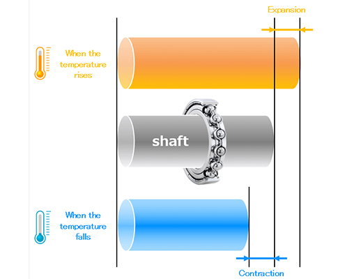
Instead of forcing the parts together mechanically, this method is through a temperature differential creates temporary clearance for hands-free assembly. Once temperatures equalize, the interference locks in. There are two ways:
Thermal calculation rule of thumb:
ΔD = D × α × ΔT
For steel (where the coefficient of thermal expansion α ≈ 12 × 10⁻⁶ /°C), , a 50 mm bore heated from 20°C to 100°C expands by:
ΔD = 50 × 12 × 10⁻⁶ × 80 = 0.048 mm
This expansion provides ample clearance for a 0.02–0.03 mm interference fit, leaving a safe margin for assembly handling time.
For large shafts (above 100 mm diameter) or components that cannot tolerate sudden impacts, hydraulic presses deliver controlled force up to hundreds of tons. The key advantage over mechanical pressing is uniform force application without hammering, which is critical for thin-walled housings vulnerable to distortion.
ISO 286 and ANSI B4.1 define standard fit designations. The tables below map the most common interference fit codes to their actual dimensional outcomes.
| Fit Designation | Shaft Tolerance | Bore Tolerance | Typical Interference Range (25 mm nominal) | Typical Application |
| H7/p6 (Light press) | p6 (+0.035 / +0.022) | H7 (+0.021 / 0) | 0.001–0.035 mm | Light-duty locating fits, easily disassembled |
| H7/r6 (Medium press) | r6 (+0.041 / +0.028) | H7 (+0.021 / 0) | 0.007–0.041 mm | Gear rims on hubs, medium-duty shafts |
| H7/s6 (Heavy press) | s6 (+0.048 / +0.035) | H7 (+0.021 / 0) | 0.014–0.048 mm | Permanent fits, bearing outer rings in cast iron |
| H7/u6 (Force fit) | u6 (+0.057 / +0.044) | H7 (+0.021 / 0) | 0.023–0.057 mm | High-torque transmission, railway wheel seats |
| ANSI Class | ISO Equivalent | Description |
| FN1 | H7/n6–p6 | Light drive fit |
| FN2 | H7/r6 | Medium drive fit |
| FN3 | H7/s6 | Heavy drive fit |
| FN4 | H7/t6–u6 | Force fit |
The tolerance bands above assume both the shaft and bore are machined to their nominal tolerance zones. In practice, a CNC turning center can hold ±0.005 mm on diameter. This means:
Consequently, the actual realized overlap (interference) narrows to 0.008–0.027 mm, which is tighter and far more predictable than the theoretical 0.001–0.035 mm range.
Tighter machining capability means more predictable interference, minimizing the safety margin a designer must reserve for tolerance stack-up. For interference fits, precision CNC machining isn’t optional: every 0.01 mm of process variation directly consumes the design margin that keeps the joint from either seizing up or slipping loose.
Material Pairing Rules
The two materials in a press-fit joint must meet two conditions: compatible elastic moduli (to share the interference strain properly) and compatible coefficients of thermal expansion (CTE) if the assembly undergoes temperature cycling.
| Material Pair | Suitability | Key Consideration |
| Steel shaft + Steel housing | Excellent | Ideal match. Identical CTE and modulus. Use lubrication to eliminate galling risks. |
| Steel shaft + Aluminum housing | Good | Aluminum has 2× the CTE of steel. At 100°C, a 25 mm aluminum bore grows ~0.03 mm more than the steel shaft. The interference can disappear at elevated temperature. |
| Steel shaft + Cast iron housing | Good | Cast iron’s graphite content acts as a solid lubricant. Lower μ (~0.10–0.15) requires higher interference for equivalent holding force. |
| Stainless shaft + Stainless housing | Caution | Extreme galling risk. Requires specialized assembly paste; never press these dry. |
| Brass shaft + Aluminum housing | Caution | Both materials are soft. Interference must be kept below 0.0005 × D to avoid plastic deformation. |
| Steel shaft + Bronze bushing bore | Excellent | Bronze’s self-lubricating properties smooth out assembly. Moderate interference works reliably. |
Surface Finish and Roughness: The μ Multiplier
The friction coefficient μ at the press interface is a function of surface roughness, lubrication, and cleanliness, not just a material constant.
For optimal performance in most steel-on-steel press fits, target Ra 0.8–1.2 µm on both surfaces. For steel-on-aluminum assemblies, keep the aluminum bore at Ra 0.8–1.6 µm to prevent galling during insertion.
| Fit Type | Clearance / Interference | Assembly Method | Disassembly | Typical Application |
| Clearance Fit (Slip fit) | Shaft < Bore (0.01–0.05 mm gap) | By hand, zero force | By hand, completely reusable | Freely rotating shafts, alignment locating pins |
| Transition Fit | Shaft ≈ Bore (±0.005 mm) | Light tapping or hand press | Light force, reusable | Motor end caps, fixture locating features |
| Press / Interference Fit | Shaft > Bore (0.01–0.05 mm overlap) | Mechanical press, heat, or cold | Destructive or via extreme force | Bearings, gears on shafts, permanent locating |
| Shrink Fit | Shaft > Bore (0.05–0.15 mm overlap) | Strict thermal assembly only | Destructive | Railway wheel sets, massive gear-to-shaft joints |
The boundary between a press fit and a shrink fit is a continuum rather than a sharp line. Below 0.05 mm of interference on a 25 mm shaft, mechanical pressing is highly efficient. Above that threshold, thermal assembly methods become mandatory.
The only surfaces requiring tight tolerances are the actual mating diameters. Flange faces, bolt patterns, and external profiles should be kept to standard machining tolerances. Tightening tolerances on non-functional features drives up production costs without adding to retention quality.
Always include a lead-in chamfer (15–30°, 0.5–2 mm deep) on the press-fit bore. Without a chamfer, the sharp edge of the bore will scrape material off the shaft during insertion, reducing your actual interference and causing severe galling.
If you are pressing a steel shaft into an aluminum housing, calculate the interference loss at peak operating temperature. A steel-in-aluminum assembly loses roughly 0.015 mm of interference per 25 mm of diameter for every 50°C rise—easily turning a tight H7/p6 fit into a loose clearance fit. In extreme cases, consider using a steel liner insert within the aluminum housing.
Disassembling a press fit permanently deforms both mating surfaces. The bore expands plastically by a fraction of the original interference. Reassembling the exact same components yields lower interference and a significantly weaker joint. For critical applications, disassembly means replacement.
A press fit that simply “feels tight” during manual assembly is not quality verification. Only two validation methods are truly reliable: monitoring the force-displacement curve on a servo press during production, or conducting a push-out test on a sample batch during validation.
An EV powertrain supplier needed aluminum end-cap housings for a 20,000 RPM traction motor. The housing had two bearing seats: a 47 mm bore for the drive-end bearing and a 35 mm bore for the non-drive-end bearing. Both required an H7 tolerance to accept bearing outer rings by thermal assembly.
The customer had been sourcing these housings from another machining shop for six months. The problem was consistent: the 47 mm bearing bore kept drifting out of tolerance. The previous shop was machining the aluminum housing — a thin-walled structure with only 3.5 mm wall thickness around the bearing bore — using a standard three-jaw chuck. Clamping pressure distorted the bore by 0.015–0.025 mm during cutting. When the part was released from the fixture, the bore sprang back, and the H7 tolerance was lost. The customer’s incoming inspection was rejecting 30% of every shipment.
VMT’s Solution
VMT took over the project and addressed the root cause that the previous shop had not resolved: clamping-induced bore distortion on a thin-walled part.
Result
Cp and Cpk for the 47 mm bore exceeded 1.67 (six-sigma capable). Three consecutive shipments passed incoming inspection with zero rejects. The customer discontinued the previous supplier and doubled the annual contract volume from 8,000 to 16,000 units.
A press fit is an interdependent system composed of three variables: machined dimensions, interface surface condition, and assembly execution. The most common point of failure is not a calculation error; it is a correct calculation undermined by practical machining variations that the designer ignored would not occur. For precision press-fit components (bearing housings, motor end caps, shaft-and-hub assemblies, and compliant-pin PCB interfaces), VMT delivers CNC-machined parts with documented Cpk, batch-level surface finish verification, and full material traceability. Explore VMT’s precision CNC machining capabilities.
What is the difference between press fit and interference fit?
Functionally, there is no difference. “Press fit” refers to the assembly process, while “interference fit” describes the dimensional state (shaft larger than bore). Every press fit is an interference fit, though some interference fits are assembled via thermal methods rather than direct mechanical force. The terms are used interchangeably in industry.
How much interference is needed for a reliable press fit?
As a baseline rule of thumb for steel-on-steel: target 0.0005–0.001 × nominal diameter. For example, a 25 mm shaft typically requires 0.0125–0.025 mm of interference. The precise value must always be calculated based on your operational torque, axial loads, material pairing, and surface finish.
What tolerance is standard for a press fit bore?
The ISO H7 standard is the benchmark bore tolerance for the vast majority of industrial press fits. The matching shaft tolerance (such as p6, r6, or s6) is then selected to dictate the final intensity of the interference. The bore serves as the baseline reference because it is inherently harder to adjust in-process than an outer shaft diameter.
Can you press fit different materials together?
Yes, but you must account for two major limitations. First, the softer material dictates your maximum allowable interference; the interface pressure must never exceed its yield strength. Second, you must calculate the exact loss of interference at peak operating temperatures caused by the differing coefficients of thermal expansion (CTE), which is especially critical in steel-and-aluminum pairings.
Why do some press fits fail after thermal cycling?
As the assembly heats up, both components expand. If the housing expands at a faster rate than the shaft (e.g., an aluminum housing paired with a steel shaft), the net interference drops. Over repeated thermal cycles, micro-fretting accumulates along the mating interface, degrading the friction coefficient and causing a progressive loss of retention force.
What surface finish is best for a press fit interface?
For steel-on-steel assemblies, target Ra 0.8–1.2 µm on both components. For mixed-material pairs, keep the softer component at Ra 0.8–1.6 µm. A turned finish is highly preferable to a ground finish because the resulting micro-texture retains necessary assembly lubricants and provides a more predictable, stable friction multiplier.

 The Ultimate Guide to Precision Acrylic CNC Machining for Industry Applicat...