In CNC machining, acrylic often appears to be the most cost-effective transparent material—cutting faster than aluminum and costing less than polycarbonate (PC). However, in precision machining, you may encounter stubborn issues such as cracking, surface hazzing, or severe dimensional out-of-tolerance due to ambient temperature fluctuations.
The core difficulty of acrylic CNC machining lies not in the cutting process itself, but in its extreme sensitivity to thermal response and residual stress. Improper feed parameters aggravate internal residual stress, dulled tools expand the heat-affected zone, and skipping the annealing process can cause components to release stress and crack weeks after assembly.
This guide aims to deeply analyze the critical factors dictating the optical clarity and dimensional stability of machined acrylic parts. We will systematically review cutting parameters, tool selection, heat treatment, and tolerance control to help you optimize designs or accurately evaluate suppliers.
Cast vs. Extruded Acrylic: Two Types of Acrylic for CNC Machining

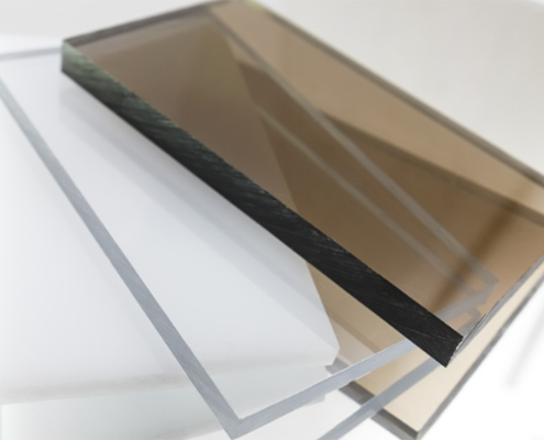
Both cast and extruded acrylic are chemically PMMA, offering about 92% light transmission and looking identical on a shelf. However, the differences emerge during CNC machining. The material choice directly dictates whether your part achieves tight tolerances and flawless clarity, or simply ends up as scrap.
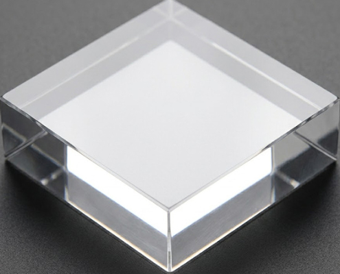
Cast Acrylic: For Optical Performance and Stress-Free Machining
Cast acrylic is produced by pouring liquid monomer between glass plates, allowing it to polymerize slowly. Because it cures without external force, the finished sheet carries almost no internal stress and has no directional grain.
For precision acrylic machining, this means three practical advantages:
- Optical Clarity: It produces the highest light transmission with minimal distortion, making it the industry standard for precision acrylic lenses, display windows, and light guides.
- Dimensional Stability: Parts hold tight tolerances and will not bow, twist, or warp after machining because there is no locked-in tension to release.
- Crack Resistance: Threaded holes, snap-fits, and thin walls are significantly less likely to develop micro-cracks (crazing) over time.
The Trade-off: Cost.
Cast acrylic is roughly 20–30% more expensive than extruded sheets, but it lowers scrap rates for high-precision parts.
Extruded Acrylic: Cost-Effective, But With Risks
Extruded acrylic is formed by forcing heated PMMA through a die at high speed and cooling it rapidly. While this continuous process yields excellent sheet thickness tolerances and lower material costs, it locks tremendous internal stress into the material.
During acrylic CNC milling, this locked-in stress causes critical issues:
- Material Melting: Heat from the cutting tool easily melts the material, causing gummy build-up and tool clogging.
- Post-Machining Warp: As material is removed, internal tension redistributes. A flat surface can bow within days, and clean edges can develop hairline fractures shortly after inspection.
- Crazing: Threaded holes and tight corners are highly prone to radiating micro-cracks weeks after assembly.
Best Applications: if extruded acrylic parts made by CNC machining, only used for simple, flat parts with relaxed tolerances and no optical requirements—such as basic industrial acrylic machine guards or structural panels.
Quick Table: Which One is Right for Your Part?
| Project Requirements for CNC machined Acrylic Parts | Recommended Material |
| Optical clarity is critical (Lenses, light guides, windows) | Cast Acrylic (Optical-grade) |
| Complex features (Threads, thin walls, internal steps) | Cast Acrylic |
| Tight flatness & dimensional stability required | Cast Acrylic |
| Purely structural, no optical function, relaxed tolerances | Extruded can work |
| Simple geometry, thick plates (>8 mm) | Extruded can work |
The Four Major Failure Modes of Acrylic CNC Machining and Their Solutions
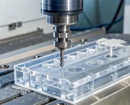
Acrylic cnc machining is a manufacturing process that uses computer-digitally controlled machine tools to highly accurately cut, drill, and mill raw acrylic materials into custom parts. But there four most common defects needs to pay attention to:
Four Common Failure Modes in Acrylic CNC Machining
- Cracking and Crazing: A dense network of tiny cracks appears on the surface or around the edges of drilled holes. This issue often shows up days after machining or during assembly, leading to part failure.
- Surface Hazing: Surfaces that are supposed to maintain high transparency turn milky or white, losing their optical clarity.
- Tolerance Drift: The parts measure perfectly right after machining, but their dimensions shift significantly when measured at different shop temperatures, exceeding the tolerance requirements.
- Warping & Bowing:The acrylic sheet bends, bows, or twists after material removal, making it impossible to meet flatness specifications.
Corresponding Machining Solutions
- How to Fix Cracking andCrazing
- Use Peck Drilling Cycles: When drilling, retract the tool every 0.5–1.0 mm to clear chips in time and prevent heat build-up.
- Optimize Corner Designs:Avoid sharp internal corners in your drawings. Keep a minimum radius of 0.5 mm at internal corners to distribute stress.
- Strictly Ban Chemical Contact: Never use isopropyl alcohol (IPA) or other organic solvents to wipe acrylic during machining or assembly. Use only mild soap and water for cleaning.
- How to Fix Surface Hazing
- Lower the Spindle Speed: Avoid cutting too fast. For a 6 mm end mill, keep the spindle speed between12,000–16,000 RPM (roughly half the speed used for aluminum).
- Use Single-Flute Cutting Tools: Single-flute end mills offer larger chip clearance, effectively preventing chip re-cutting and friction heat.
- Enforce Mist Cooling: Always use compressed air or a coolant mist pointed directly at the tool tip during machining. Never dry-cut acrylic.
- How to Fix Tolerance Drift
- Strictly Control Ambient Temperature: The temperature in the machining shop and inspection room must be controlled within ±2°C to prevent dimensional deformation due to acrylic’s high thermal expansion coefficient.
- Adopt a Step-by-Step Process: Rough-machine the part first, leaving a 0.2–0.3 mm stock allowance. Let the part rest for 30 minutes to dissipate heat before taking the final precision pass.
- How to Fix Warping andBowing
- Prioritize Cast Acrylic: Choose cast acrylic, which has exceptionally low internal stress, at the sourcing stage. Avoid extruded materials that easily warp during machining.
- Arrange Pre-Machining Annealing: For parts with strict flatness requirements, heat the raw sheet to around 80°C, hold it, and cool it down slowly over several hours to release original internal stresses before cutting.
Post-Processing of Acrylic CNC Machined Parts: Vapor, Flame, and Mechanical Polishing
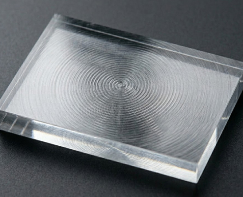
Acrylic parts directly off a CNC machine are dimensionally accurate but translucent due to visible tool marks. To achieve complete transparency or specific surface effects, you must select the right post-processing method based on your part’s geometry and application:
- As-Milled Finish
- What it is: The part is left exactly as it comes off the machine, showing minor tool path lines.
- Best For: Structural brackets, internal enclosures, or any component hidden inside the final assembly. It adds zero cost and zero lead time.
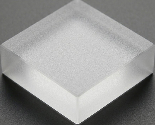
- Bead Blasting
- What it is: Blasting the surface with fine media to create a uniform, frosted matte texture.
- Best For: Eliminating tool marks entirely and creating a premium non-glare look. Note: This process irreversibly destroys transparency; a bead-blasted part cannot be polished back to clear.
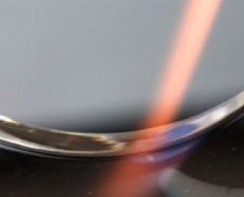
- Flame Polishing
- What it is: Passing a high-temperature flame quickly across the machined edges to melt and re-flow the outermost layer into a glass-like finish.
- Best For: External edges and simple flat surfaces. It is highly cost-effective and fast, but it cannot reach deep internal features or complex cavities.
- Vapor Polishing
- What it is: Exposing the component to specialized solvent vapors in a sealed chamber, allowing the chemical to briefly melt and smooth the polymer layer.
- Best For: Achieving maximum optical clarity on internal geometries. This is the only reliable method for clearing out internal bores, deep manifold channels, and complex undercut surfaces.
- Mechanical Polishing andSanding
- What it is: Utilizing progressively finer sandpaper grits followed by a rotating cloth wheel and polishing compound.
- Best For: Flat external surfaces requiring a flawless, mirror-like finish. While highly effective for simple shapes, it is labor-intensive and not suitable for intricate details.
PMMA Properties and What They Mean for Machining
As we’ve explored, cast acrylic is good for precison parts while extrude acrylic is only for simple and lossen tolerance components. And here is a simple suplementary table for properties of cast acrylic and the impacts to CNC machining:
| Property | Cast Acrylic (PMMA) | Machining Implication |
| Tensile Strength | 55 MPa | Moderate. Clamping force must be distributed; point loading cracks the part |
| Elongation at Break | 2.70% | No plastic deformation before fracture — no warning, just a sudden crack |
| Hardness (Rockwell) | M80–M100 | Holds threads but cracks if tapped aggressively. Use acrylic-specific taps |
| Heat Deflection Temp | 85°C | The cutting zone temperature ceiling. Exceed it and the surface melts or hazes |
| Light Transmittance | 92% | Achievable only after polishing; as-milled surfaces scatter 15–30% of light |
| Thermal Expansion | 70–80 × 10⁻⁶ /°C | Six times steel. Every tolerance measurement must reference a specific temperature |
| Density | 1.18 g/cm³ | Under half the weight of glass. Enables larger parts with less support structure |
Application-Specific Considerations for Machined Acrylic
Different industries have unique requirements for acrylic components. When designing or sourcing parts, consider these sector-specific guidelines:
- Medical CNC AcrylicParts
- Key Components: Fluidic manifolds, diagnostic cuvettes, and surgical tool handles.
- Requirements: The raw material must carry USP Class VI or ISO 10993 biocompatibility certification. To prevent metallic contamination during production, parts should be machined using dedicated tooling that has never touched metal. Full lot traceability from the raw material block to the final inspection is standard practice.
- Optical CNC AcrylicParts
- Key Components: Lens housings, beam splitters, and prism mounts.
- Requirements: Functional faces require an optical-grade surface finish, often verified via interferometer testing to ensure post-machining stress has not warped the surface. If your project requires stray-light control, opaque black acrylic is available, though it machines slightly differently than clear grades due to the carbon filler.
- Automotive orOutdoor CNC AcrylicComponents
- Key Components: Exterior lighting housings and trim pieces.
- Requirements: Outdoor applications require UV-stabilized acrylic grades to prevent yellowing over time. This is a material choice rather than a machining fix. Additionally, interior automotive components must comply with standard flammability regulations (such as FMVSS 302) with documented proof per lot.
- Industrial CNC AcrylicComponents
- Key Components: Automation enclosures and clear protective shields.
- Requirements: For basic industrial acrylic machine guards, structural strength and impact resistance matter more than perfect optical clarity. These components must meet strict physical dimensional tolerances to ensure seamless integration on the assembly line and specify premium PMMA(or the tougher Polycarbonate)to prevent micro-cracking at fastening points.
Top Design Tips for Preventing Acrylic Parts Failure
To ensure your custom acrylic components are both manufacturable and reliable during assembly, integrate these critical design rules directly into your 3D models and blueprints:
- Wall Thickness Limitsof CNC Acrylic Parts
- Rule: Maintain a minimum wall thickness of5 mm.
- Tip: Any wall thinner than5 mm lacks the structural integrity to withstand typical handling and assembly forces. For thin-walled features between 0.5 mm and 1.5mm, ensure they are well-supported by surrounding geometry to minimize flexing.
- Internal Corner Radii
- Rule: Specify a minimum internal corner radius of5mm. For deep pockets, the corner radius should scale up with the depth.
- Tip: Sharp 90℃ internal corners act as severe stress concentrators. Under mechanical loads or thermal expansion, cracks will almost always initiate at these points. A deep pocket (e.g., 10mmdeep) paired with a tiny 5mm radius creates high localized tension; increasing the radius helps distribute stress evenly.
- ReasonableTolerance Allocation
- Rule: Reserve tight tolerances (±01mmto ±0.02mm) exclusively for functional features. Use generous tolerances (±0.05mm to ±0.1mm) for non-mating geometry.
- Tip: Due to acrylic’s high thermal expansion coefficient, calling out tight tolerances across an entire drawing dramatically increases manufacturing costs without improving performance. Focus precision only on critical mating surfaces, press-fit alignment bores, and optical interfaces.
- Threaded Hole Optimization
- Rule:Use threaded inserts (such as helicoils or brass inserts) for any hole that will be assembled and disassembled more than five times over the part’s service life.
- Tip: Acrylic is a brittle polymer, and its machined internal threads can easily strip or develop micro-cracks at the root under repeated fastening torque. For small threads (under M4) intended for permanent assembly, specify thread depths at least 2 × to 2.5 × the screw diameter to ensure sufficient holding power.
- Part Size and Modular Layout
- Rule: Design large assemblies as multiple split components joined by solvent bonding or mechanical fasteners if they exceed the maximum block footprint of 1300 × 635 × 635 mm.
- Tip:For oversized enclosures or display structures, a modular approach is superior, as large, monolithic acrylic parts are highly susceptible to cumulative thermal expansion and warp during shipping and installation.
Table of Cost Factors for CNC Acrylic Parts
| Cost Driver | Impact | How to Optimize |
| Material Grade | Cast costs 20–30% more than extruded; UV and medical grades add further premium | Use cast for all machined parts. The material difference is recovered through lower scrap rate |
| Tolerance Band | Tightening from ±0.05 mm to ±0.01 mm adds thermal stabilization time and finish passes | Reserve ±0.01 mm for functional interfaces only |
| Surface Finish | Vapor polishing: 3–5× as-milled cost. Flame: 1.5–2×. Bead blasting: 1.2–1.5× | Polish only surfaces the user sees or light passes through |
| Annealing | Adds 4–8 hours of oven time | Required for flatness <0.1 mm/100 mm or wall thickness <2 mm |
| Quantity | 1–10 units: setup dominates. 100+: unit cost drops significantly | Validate design with 3–5 prototypes before committing to a production batch |
VMT CNC Machining Factory Case Study
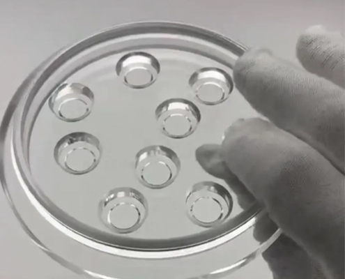
Custom Acrylic Enclosure for a Laboratory Analytical Instrument
A laboratory instrument manufacturer required 200 custom acrylic enclosures for a new spectroscopy device. The enclosure needed to serve three functions simultaneously: a crystal-clear safety barrier for the operator, an environmental seal against laboratory humidity, and a precision-mounting frame for delicate internal optical alignment components.
The enclosure design combined several features that individually make acrylic difficult to process and collectively made it a challenging project:
- Fragile Proportions: The walls were 2.5 mm thick across a large 300 × 200 mm face—thin enough that cutting vibrations could initiate micro-cracks, yet thick enough that internal raw material stress was significant.
- Tight Tolerances: The blueprint called for eight M3 threaded holes for optical mount attachment, positioned within a strict ±0.05 mm of their nominal locations.
- Dual-Surface Clarity: The enclosure featured a deep internal pocket with a viewing window that required flawless optical clarity on both the external and internal faces.
- The Delayed Failure: The previous supplier’s samples had arrived looking acceptable, but developed visible stress cracks radiating from the threaded holes after being in the laboratory for two weeks—well after the batch had already passed inspection.
The Approach by VMT
To overcome these challenges, our engineering team targeted the root causes at every stage of production, starting with strict material verification:
- Every acrylic blank underwent a polarized-light inspection at raw material receiving to verify low internal stress. Blanks showing stress birefringence were rejected immediately before machining—eliminating the hidden defect that the previous supplier had overlooked.
- During the CNC machining phase, VMT utilized sharp, single-flute carbide end mills running at 14,000 RPM, with continuous pressurized air-mist cooling directed precisely at the tool tip. This setup kept the cutting zone well below critical temperatures, successfully preventing the surface hazing that would have compromised the viewing window.
- To resolve the cracking issue, the M3 threaded holes were produced using acrylic-specific thread-forming taps rather than traditional cutting taps. VMT implemented a precise peck-tapping cycle (advancing 0.5 mm, then retracting to clear), eliminating the micro-cracks along the thread roots that had plagued the previous supplier’s parts.
- Furthermore, to hold the 0.08 mm flatness requirement across the 300 × 200 mm faces, the blanks received a pre-machining thermal annealing cycle: a controlled ramp to 80°C, a 3-hour hold, and a slow cool-down over 4 hours. After machining, the viewing window area underwent vapor polishing to restore full optical clarity on both faces, while the non-functional geometry of the enclosure was left as-milled to manage costs.
The Result
All 200 custom enclosures were successfully shipped within the agreed schedule. After 12 months of active field use in end-user laboratories, zero parts exhibited stress cracking—completely eliminating the failure mode that had derailed the previous supplier’s batch. Also, the optical viewing windows maintained consistent clarity with no hazing or yellowing reported.
Final Thoughts
This article provides a comprehensive manufacturing, purchasing, and design guide for acrylic CNC machining, covering design rules, failure prevention, troubleshooting techniques, and cost considerations. Partnering with an experienced CNC acrylic service ensures that the right material, annealing steps, and cutting parameters are locked in from day one, delivering reliable cnc acrylic components that integrate seamlessly into your final assembly. VMT provides precision CNC machining of cast acrylic (PMMA) for medical devices, optical instrumentation, automotive lighting, and industrial equipment. Single-flute cold machining, in-house vapor polishing, thermal annealing, and full material traceability support prototype through production quantities. Request a DFM review for your acrylic component design.


 Acrylic vs. Polycarbonate CNC Machining: How to Choose the Right Clear Plas...