Machining Polycarbonate: A Complete Guide to CNC Machining Polycarbonate Parts
By JunWen Liu | Jun. 26, 2026

With its exceptional impact resistance (250 times that of ordinary glass) and excellent optical clarity, polycarbonate (PC) has become a highly popular material for medical housings, optical lens barrels, and automotive components.
However, flawlessly transforming this high-performance material into high-precision CNC parts is not as easy as it sounds. A common scenario goes like this: the edges of a freshly machined workpiece inexplicably turn white, the surface of a supposedly transparent part mysteriously cracks, or the component embrittles and fails entirely after being coated with certain cutting fluids. Behind these issues lies PC’s sensitivity to temperature, stress, and chemical exposure.
This article will introduce you to the core processes, essential troubleshooting guides, and real-world factory case studies for CNC machining PC components. In addition, you will gain comprehensive guidance on material selection, the differences between PC and other common plastics, and its applications and choices.
Polycarbonate is a class of thermoplastic polymers containing carbonate groups (-O-CO-O-) in their main chain. The most common is Bisphenol A polycarbonate (BPA-PC), known by commercial names such as Makrolon (Bayer/Covestro) and Lexan (SABIC).
| Characteristic | Details |
| Density | Approx. 1.20 g/cm³ |
| Melting Point | Approx. 295°C |
| Glass Transition Temperature | Approx. 150°C |
| Impact Resistance | Outstanding: 250 times that of ordinary glass, and 30 times that of acrylic (PMMA) |
| Temperature Resistance | Long-term use: −40°C to 135°C Short-term use: Up to 150°C |
| Light Transmission | 88–90% light transmittance, very close to glass |
PC is a category of materials rather than a single grade; different grades offer distinct properties and suit different applications. Please confirm your specific application scenario before finalizing your material selection:
| Grade Category | Typical Application Examples |
| Transparent PC (Makrolon) | Optical housings, light guides, inspection windows |
| Black PC | Structural enclosures, brackets, gears |
| PC GF20 (20% Glass Fiber) | High-rigidity load-bearing components, snaps/clips |
| Flame Retardant PC (UL94 V-0) | Electrical enclosures, power supply housings |
| Medical Grade PC (ISO 10993) | Medical device housings, surgical handles |
Notes for Selection:
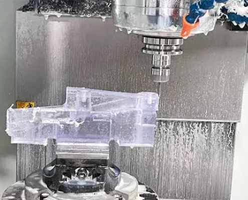
The complete CNC workflow for PC parts can be broken down into 6 essential steps:
Incoming Inspection→ Pre-drying → Rough Machining→ Finish Machining→ Annealing (Stress Relief)→ Surface Finishing
Every step is vital to the process:
Purpose: Check the initial state of the raw PC material or sheets. The focus is on detecting surface scratches, bubbles, impurities, and ensuring that the dimensional tolerances of the raw material meet machining requirements.
Process Parameters: 120°C for 4 hours.
Necessity: PC (polycarbonate) is highly hygroscopic; stored materials can reach a moisture content of up to 0.2%. If you skip this step and go straight to cutting, the frictional heat generated during machining will cause the internal moisture to vaporize, leading to internal bubbling and surface cloudiness.
Process Requirements: Rapidly remove the bulk of the material. To avoid a massive accumulation of cutting heat from single-pass cutting—which causes edge whitening (commonly known as a “cloudy edge”)—it is essential to leave a 0.3mm finish machining allowance during roughing.
Process Requirements: Based on the rough machining stage, perform high-precision machining to cut away the reserved 0.3mm allowance in a single pass. This ensures both the final dimensional tolerances and a smooth, high-gloss appearance on the cut surface.
Process Parameters: 120°C for 2 hours.
Necessity: CNC cutting generates significant internal stress. Without annealing, parts may experience unprovoked cracking weeks after assembly on equipment (known as “delayed cracking”). Annealing allows the molecular chains to relax and eliminates internal stress. This step is a mandatory standard for all high-precision PC parts with tolerances ±0.1mm.
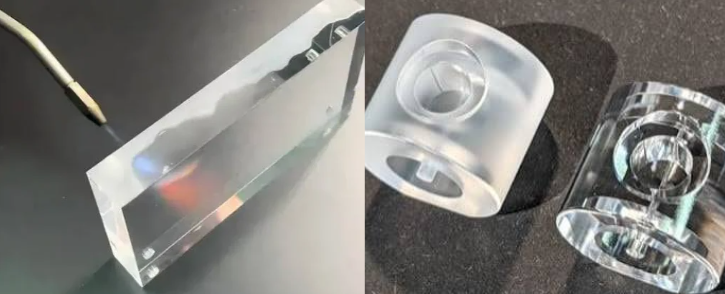
Purpose: The factory will confirm the final requirements of your drawings to perform post-processing on the completed PC parts. This includes polishing (such as chemical, flame, or mechanical polishing to restore high transparency), sandblasting, silkscreen printing, or post-polishing coating to enhance the part’s appearance, texture, and wear resistance.
| Parameter | Rough Machining | Finish Machining |
| Tooling | Carbide single-flute end mill (Single flute preferred for fast chip evacuation) | Brand new Carbide or PCD (Polycrystalline Diamond) tools |
| Spindle Speed (6mm tool) | 12,000–15,000 RPM | 15,000–18,000 RPM |
| Feed Rate | 1,500–2,500 mm/min | 800–1,500 mm/min |
| Depth of Cut (per pass) | 0.5–1.5 mm | 0.1–0.3 mm |
| Cooling | Compressed air + Water-soluble coolant (Non-aromatic) | Pure compressed air (Avoid coolant residue to prevent stress cracking) |
| Indicator | Standard Capability | Precision Level (Higher Cost) |
| Dimensional Tolerance | ±0.05 mm | ±0.02 mm |
| Hole Position Tolerance | ±0.05 mm | ±0.02 mm |
| Surface Roughness (Ra) | 0.8 μm (As Machined) | 0.4 μm (After Vapor Polishing) |
| Maximum Machining Size | 400 × 400 × 200 mm | — |
| Minimum Inner Hole Dia. | 0.5 mm | — |
| Wall Thickness Variance | ±0.05 mm | — |
Core Advantages of PC CNC Machining
| Advantage | Details | Engineering Benefit |
| Ultra-High Impact Resistance | 250× that of glass, 30× that of acrylic (PMMA). | Parts are extremely rugged and highly resistant to cracking or chipping during machining. |
| High Machining Tolerance | High melting point of 295°C (compared to PMMA at only 160°C). | Less prone to tool sticking or melting during cutting; machining yield rates can exceed 95%. |
| Excellent Post-Processing | Supports vapor polishing, painting, silkscreen printing, plating, etc. | Extremely easy to restore high transparency or enhance surface texture through post-processing. |
| Eco-Friendly & Sustainable | Leftover scraps can be 100% recycled and re-granulated. | Aligns perfectly with green manufacturing and modern ESG trends. |
Disadvantages of PC CNC Machining and How to Avoid Them
| Disadvantage | Cause | How to Avoid It |
| Easily Scratched Surface | PC inherently has a low surface hardness (pencil hardness is only B grade). | Apply a subsequent hard coating, or switch to PMMA for purely cosmetic parts. |
| Internal Stress Cracking | Excessive clamping force, deep cutting depths, or superimposed external forces during assembly. | Perform post-machining annealing (120°C for 2 hours) and optimize cutting parameters. |
| Edge Whitening (Cloudy Edges) | Single-pass cutting depth exceeding 0.3mm, causing massive cutting heat accumulation. | Separate rough and finish machining; leave a 0.3mm allowance during roughing and clear it in a single finish pass. |
| Environmental Stress Cracking (ESC) | Exposure to amine-based coolants or alcohol-based cleaning agents. | Strictly use specialized non-amine coolants; never use alcohol for cleaning. |
| Higher Material Cost | 3 to 5 times more expensive than ABS; 1.3 to 1.8 times more expensive than PMMA. | Best reserved for low-volume, high-value-add precision components. |
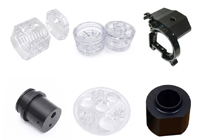
Due to its high impact resistance, excellent transparency, and great machinability, Polycarbonate (PC) is widely used across various industries. Here are some key examples:
In the selection and machining of transparent engineering plastics, PC, PMMA (Acrylic), and ABS are materials that are easily confused. However, their machining characteristics and application scenarios differ significantly. Understanding these differences can help you select the most suitable material for part production, preventing mass-production yield risks and after-sales cost liabilities.
| Comparison Dimension | Polycarbonate (PC) | Acrylic (PMMA) |
| Impact Resistance | 250× glass, 30× acrylic | 17× glass, brittle |
| Light Transmittance | 88–90% | 92% (slightly higher than PC) |
| Surface Hardness | Pencil hardness B, easily scratched | Pencil hardness 3H, scratch-resistant |
| Long-Term Temp Resistance | −40°C to 135°C | −40°C to 100°C |
| Melting Point | 295°C | 160°C |
| Machining Tolerance | High (high melting point, less tool sticking) | Low (low melting point, prone to melting and tool sticking) |
| Yield Rate | ~97% | ~85% (complex parts) |
| Unit Price | Medium-High (~2.50–3.50 USD/kg) | Medium (~1.50–2.00 USD/kg) |
| Typical Applications | Machine guards, lens barrels, medical housings | Display cases, lamp shades, outdoor windows |
| Comparison Dimension | Polycarbonate (PC) | ABS |
| Impact Resistance | 250× glass | 8× glass |
| Light Transmission | Available in transparent and opaque | Opaque (natural ivory white) |
| Temp Resistance | Long-term 135°C, short-term 150°C | Long-term 80°C, short-term 100°C |
| Flame Retardancy | Up to UL94 V-0 | Typically HB |
| Machining | High melting point (295°C), cutting heat requires strict control | Low melting point (~230°C), wide machining window |
| Surface | Easily scratched | Good |
| Cost | High | Low |
| Typical Applications | Transparent covers, medical, electrical | Consumer electronics housings, home appliances, toys |
A well-known machine vision company in Germany developed an industrial camera. Its core component, the “PC material lens barrel,” was initially produced by another supplier using traditional injection molding. However, after the first batch of 200 finished parts was delivered from the mold, the client encountered severe quality issues: within just about 2 weeks of mounting lenses onto the bayonet interface, they hit an 18% mass-cracking return rate. Urgently needing a new partner to solve this cracking problem, the client contacted VMT.
Upon receiving the defective samples sent by the client, our engineering team immediately performed cross-sectioning and stress analysis, uncovering three root causes for the cracking:
To address these design flaws and process defects, our team advised the client to abandon the injection molding approach and switch to a “CNC Precision Machining + Structural Optimization + Mandatory Annealing” process:
Ultimately, after the first batch of 500 CNC-machined parts was delivered, the client reported “0 cracking” over 6 months of on-device testing. Today, this project has been scaled up by the client into a long-term mass production order of 8,000 pieces per month.
This article has systematically introduced the complete path of CNC machining PC parts across seven dimensions: material characteristics, CNC machining principles, application scenarios, comparisons with PMMA/ABS, typical case studies, pros and cons balancing, and frequently asked questions.
We hope this guide provides practical assistance during your material selection, process evaluation, and supplier audits. You no longer have to worry about the headaches of whitened PC part edges, clamping cracks, or unstable mass-production yields.
Welcome to send your 2D drawings (PDF file) or 3D drawings (IGS/STP/STEP file) to our engineering team. We are happy to provide free DFM reviews and process optimization recommendations.
The technical information and manufacturing advice shared on the VMT website are for general guidance only. While we strive for accuracy, VMT does not guarantee that the processes, tolerances, or material properties mentioned are applicable to every specific project. Any reliance you place on such information is strictly at your own risk. It is the buyer’s responsibility to provide definitive engineering specifications for any production orders. Final specifications and service terms shall be subject to the formal contract or quotation confirmed by both parties.
What should I do if the Polycarbonate surface turns white after machining?
This is a classic sign of excessive cutting heat. Check these three areas for troubleshooting:
If the whitened part only has cosmetic issues, its transparency can be restored using Vapor Polishing.
What is the tightest tolerance achievable in Polycarbonate machining?
Our standard recommended tolerance is ±0.05mm, with a precision limit of up to ±0.02mm. However, please note that PC parts experience a post-machining shrinkage of 0.1–0.3% (primarily caused by moisture absorption and stress relaxation). Therefore, when drawing tolerances are strictly required to be ±0.02mm or less, we typically add a low-temperature aging process (60°C for 24h) to stabilize dimensions.
Why do Polycarbonate parts crack on their own 2–4 weeks after being installed on equipment?
This is highly likely Delayed Cracking, which is rooted in a combination of residual internal machining stress and superimposed external assembly forces. How to avoid it:
How do I choose between Polycarbonate and Acrylic (PMMA)?
If you need impact resistance (such as machine guards or outdoor enclosures), PC is recommended. If you need maximum light transmittance and do not require high impact resistance (such as display cases or light covers), PMMA is recommended.
What is the Minimum Order Quantity (MOQ) for Polycarbonate machining?
Our factory has No MOQ for PC parts. You can start with a sample part to verify assembly before deciding on mass production. Volume production parts are eligible for tiered pricing.
What certifications can your Polycarbonate parts pass?
Our factory holds the ISO 9001:2015 quality management system certification, alongside AS9100 (Aerospace) and IATF 16949 (Automotive) system certifications, making us fully qualified for aerospace and automotive industry clients.
At the material level, our entire product line is RoHS / REACH compliant, and we can provide declarations of conformity and SVHC (Substances of Very High Concern) lists for clients exporting to the EU and North America.

 High-Density Polyethylene (HDPE) Properties, Advantages, and CNC Machining ...