Aluminum Surface Finishes: 8 Common Traps for CNC parts (And How to Avoid Them)
By JunWen Liu | Aug. 13, 2026
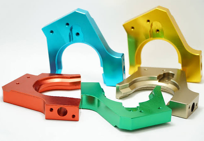

Aluminum CNC parts are quite popular among aerospace, electronics, automotive, or medical uses, as you might also know their advantages for being lightweight, having good strength, being easy to machine (cost-friendly), and easy to surface-treat (gaining wear resistance, corrosion resistance, or an aesthetic look). But with so many types of aluminum surface finishes you could encounter, ignoring finish effects like film thickness, color differences on different grades, or other traps can bring your aluminum products surface defects or budget overruns. In this blog, you will understand the 8 most common traps for aluminum surface finishes, along with actionable tips on how to avoid them. At the end, we will also share a case study on how our factory solved a color fading issue for a client’s anodized aluminum motorcycle wheel hubs.
This is a quite common issue in aluminum surface finishing that you could encounter (many of our clients also come to us with this issue). Except for surface finishing supplier reasons (when the quality is okay when delivered and received), this could happen mostly because of the use environments of the aluminum components:
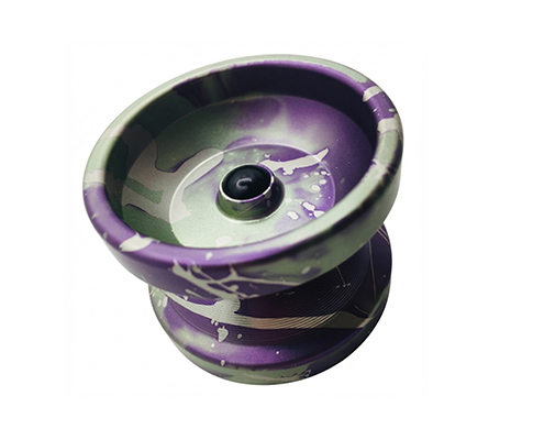
But how can you avoid this finish issue from happening? One way is to choose other more durable aluminum finishes (like powder coating). Other methods are listed below if an anodizing surface finish is a must:
This is simple to understand that the final finished aluminum parts must account for the coating or film thickness. While this usually isn’t a concern when you partner with a qualified supplier, since an experienced factory will factor this in to prevent fit issues with precise hole locations, threads, or mating parts. Here is a table listing common types of surface finish of aluminum with their film thickness in case that you have the needs of “pre-finish tolerances” or “post-finish tolerances” specifying:
Aluminum Surface Finish Chart of Typical Film Thickness (Per Side)
| Aluminum Surface Finish Types | Process Category | Film Thickness | Tolerance Impact & Tips |
| Type II Anodizing (Standard) | Electrochemical | 5 – 25 µm (0.0002″ – 0.001″) | Moderate: ~50% grows into the metal and 50% builds on top. Adjust tight tolerances accordingly. |
| Type III Hardcoat Anodizing | Electrochemical | 25 – 50 µm+ (0.001″ – 0.002″+) | High: Significant dimensional increase. Precise internal threads and reamed holes usually require masking. |
| Powder Coating | Protective Layer | 50 – 120 µm (0.002″ – 0.005″) | Very High: Substantial layer. Mating surfaces, small holes, and threads must be masked before spraying. |
| Alodine / Chem Film (Chromate) | Chemical Conversion | 0.5 – 1.5 µm (0.00002″ – 0.00006″) | Negligible: Does not noticeably change part dimensions. Ideal for tight-tolerance conductive areas. |
| Bead Blasting | Mechanical Treatment | Net Zero (Removes ~1–3 µm) | Low to Moderate: Slightly alters surface texture and roughness (Ra) rather than adding material. |
| Brushing | Mechanical Treatment | Net Zero (Removes ~2–5 µm) | Low: Mechanical abrasion removes a tiny layer of metal to create fine parallel line patterns. |
| Polishing | Mechanical Treatment | Net Zero (Removes ~2–5 µm) | Low: Micro-abrasion smooths out surface peaks; slightly reduces outer dimensions on sharp edges. |
| Electroplating | Plating / Deposition | 5 – 25 µm (0.0002″ – 0.001″) | Moderate: Builds up a metallic layer (e.g., nickel or chrome). Requires consideration for high-precision thread fits. |
| PVD Coating | Vapor Deposition | 1 – 5 µm (0.00004″ – 0.0002″) | Very Low: Creates an extremely thin, high-hardness film with minimal impact on tight engineering tolerances. |
Here let’s just take the most popular aluminum grades, 6061 and 7075, as examples. These two are often produced for lots of parts, and the key difference is that 7075 (an aerospace alloy) has higher strength than 6061 (used for daily-use strength).
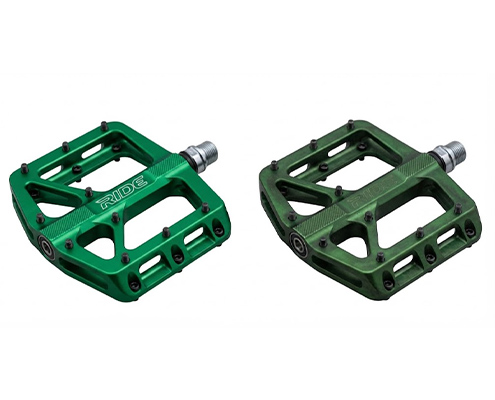
The thing is that for many consumer or decorative aluminum parts with a colored surface, you are better off choosing 6061. This is because 7075 has a high zinc content, which dissolves differently in the anodizing bath, creating an uneven pore structure and a slightly darker base film. As a result, color adhesion and color consistency will be negatively affected.
What you can do is try to choose the same grade of aluminum(better the 6061) for the same series of decorative products (and ask the factory to use the same batch of aluminum bars, as their chemical composition will be exactly the same).
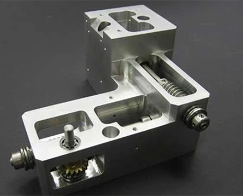
When you get the quote or invoice, you might notice an extra fee called “Masking Charge” if the aluminum parts have features like tight-tolerance holes, internal or external threads, or precise mating surfaces. Don’t worry, this isn’t a hidden trick yet a complete necessity!
This happens because the factory cannot just throw the whole part directly into an anodizing, plating, or powder coating tank. If they do that, powder coating will clog your fine threads so bolts can’t screw in, or anodizing will build up thickness that ruins your tight hole tolerances (and turns conductive contact points non-conductive).
To prevent these bad consequences, workers at the factory have to do masking first. This is a careful, manual process where operators hand-apply high-temperature tapes, rubber plugs, or custom stoppers onto the critical holes, threads, and sealing surfaces to keep them completely untouched by the coating. Since this takes extra labor and time, it adds to your processing cost. This tells you to focus on which exact key areas need masking (be caution of your holes, or threads designs), otherwise this can brings you extra fees.
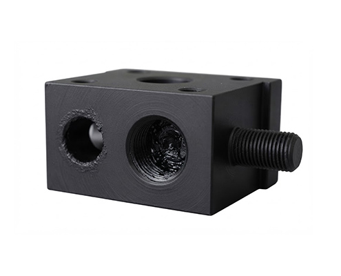
It is important to mention that if the finished aluminum component needs to conduct electricity, regular anodizing is simply not suitable. Anodizing creates an aluminum oxide layer that acts as an electrical insulator. So, relying on regular anodizing will cause your assembly to fail electrically when the design requires electrical grounding, EMI shielding, or conductive contact points.
To deal with the “conductivity or not” issue, you need to choose the right finish based on your specific conductivity needs:
But the most convenient way is to just tell the factory or clearly state on your 2D drawings: “Keep Area X Electrically Conductive” or specify “Chem Film per MIL-DTL-5541” for grounding features, so the supplier knows exactly how to handle the surface.
In actual CNC production, a sharp outer corner without a fillet or chamfer(like, a 90。corner) is a major hazard for surface finishes. For example, when anodizing, the oxide layer grows perpendicular to the aluminum surface, which leaves a thin, weak gap right at a sharp edge. Another example is , for powder coating, surface tension causes the liquid paint to pull away, leaving sharp edges with an ultra-thin layer that easily chips off.
Fortunately, you usually don’t have to worry about this when to work with an experienced CNC service supplier. During the DFM (Design for Manufacturability) review before machining ever starts, factory engineers will identify these sharp profiles and suggest adding a 0.5 mm chamfer (0.5 mm * 45。) or edge radius (R 0.5 mm). This ensures surface smooth transitions so coatings can build up evenly and stay durable.
This is a condition that often occurs with thin-walled precision aluminum parts. For thin-walled parts (<1.5 mm), the factory generally will not recommend high-pressure bead blasting (even if you desire a heavy matte texture or deep satin look). In addition, choosing high-pressure bead blasting for aluminum parts with too many blind holes or deep slots can easily lead to trapped abrasive media inside. Therefore, you should either switch to a finish that can be achieved with gentle blasting (aluminum bead blasting typically uses low pressure and rounded media) or adjust your part design.
When you notice two “white spots” or conductive contact marks on visible areas of a part after anodizing, do not mistake them for surface defects. This happens because the parts must be powered through metal racks during the anodizing process, and the rack contact points cannot form an oxide film. Therefore, the best recommendation is to clearly mark “racking location allowed” on your drawings (usually on internal walls or subtle bottom surfaces where clamping is permitted).
Solving Anodized Color Fading for Motorcycle Wheel Hubs
When an motorcycle client came to us, they were facing a quality headache. Their custom 6061-T6 aluminum motorcycle wheel hubs with a vibrant red anodized finish, but the parts faded and turned a washed-out pink after just a few weeks of outdoor riding. And they had tried switching between several finishing vendors, but every batch suffered the same color degradation.
After reviewing the application and analyzing the failed samples, our engineers found two main root causes.
To solve this, we upgraded both the chemical recipe and process controls:
The optimized hubs successfully passed 500 hours of accelerated UV weathering tests (ASTM G154) and 96 hours of salt spray testing (ASTM B117) with zero color change or corrosion. The client’s red wheel hubs then can keep excellent finish under long-term outdoors uses.
Achieving the best aluminum surface finishes for your CNC parts needs to avoid these common traps—from considering film thickness and alloy differences to specifying proper masking, conductivity, and racking locations. After fully understand these ones, I believe you can better ensure your parts turn out exactly as designed, both visually and functionally.
What’s more important, partnering with an experienced CNC supplier who understands DFM and surface treatment details can save lead time, avoid costly rework, and protect the brand reputation. Have a challenging aluminum project or questions about custom surface finishes? [Contact our engineering team ] to get expert DFM feedback and a quick quote for your next build! [2D Drawings (PDF files), 3D Drawings (IGS/STP/STEP files)]
 WhatsApp/WeChat/Mobile:
+86-15099911516
WhatsApp/WeChat/Mobile:
+86-15099911516 Tel: 86-150-9991-1516
 QQ: 939020977
 E-Mail: service@vimetal.com.cn


Q1: What factors should I consider when selecting a surface finish for aluminum parts?
When choosing a surface finish for aluminum, you should mainly consider four key factors: environment (corrosion and UV exposure requirements), functionality (electrical conductivity, wear resistance, or strict dimensional tolerances), aesthetics (color, texture, or reflectivity), and budget. For instance, outdoor structural components often need anodizing or powder coating, while internal electrical contact pads require Chem Film (Alodine).
Q2: How does the surface finish of sand cast aluminum parts vs CNC parts compare?
The surface finish of sand cast aluminum parts vs CNC parts differs significantly in roughness and consistency. Sand casting yields a relatively rough, granular, and porous texture (typically Ra 6.3–12.5 µm), which usually requires heavy post-processing like bead blasting or grinding to achieve a clean look. In contrast, CNC machined parts offer a much smoother, precise surface (typically Ra 0.8–3.2 µm or better) with uniform tool marks, making them ideal for high-precision mating surfaces and immediate anodizing.
Q3: What is the difference between aluminum die casting surface finish vs CNC parts?
In comparing aluminum die casting surface finish vs CNC parts, die-cast aluminum parts generally have a smooth, semi-matte as-cast skin (Ra 1.6–3.2 µm) suitable for direct powder coating or painting. However, die castings often harbor internal micro-porosity near the surface layer. If you heavily machine or anodize a die-cast part, this porosity can become exposed, causing blistering or white spots. CNC parts are machined from solid wrought aluminum stock (like 6061-T6), providing a dense, non-porous surface that anodizes much more consistently.
Q4: How does aluminum extrusion surface finish vs CNC parts differ prior to anodizing?
Looking at aluminum extrusion surface finish vs CNC parts, extruded profiles typically feature continuous die lines or longitudinal streaks along the extrusion direction. CNC parts display visible milling cutter patterns instead. While both can be anodized, extruded parts often require alkaline etching or bead blasting prior to anodizing to hide those directional die lines and create a uniform matte appearance.
Q5: Can I apply an aluminum surface finish to conductive grounding areas?
Standard anodizing creates an aluminum oxide layer that acts as an electrical insulator, making it unsuitable for grounding features. If your part requires an aluminum surface finish with electrical conductivity, you should specify Chem Film (Chromate Conversion Coating / Alodine) per MIL-DTL-5541, or use a selective masking approach to leave grounding pads uncoated.
Q6: Which aluminum surface finish is best for hiding CNC tool marks?
A combination of bead blasting followed by Type II anodizing is the most popular solution. The bead blasting process homogenizes the metal surface, while anodizing adds corrosion resistance and color without exposing the underlying tool marks.
 Written By JunWen Liu
JunWen Liu holds a Mechanical Engineering degree from Esslingen University of Applied Sciences and spent seven years as a CNC Process Engineer, accumulating extensive hands-on experience. She now shares that knowledge through her writing, drawing from real problems she encountered on actual projects. Outside of work, she enjoys hiking and is always chasing the next summit view.

 Aluminum Sheet Metal: How It Contributes to Aluminum Prototyping and CNC Pa...