PTFE Machining Guide: Properties, Applications, and Engineering Issues
By JunWen Liu | Nov. 18, 2026
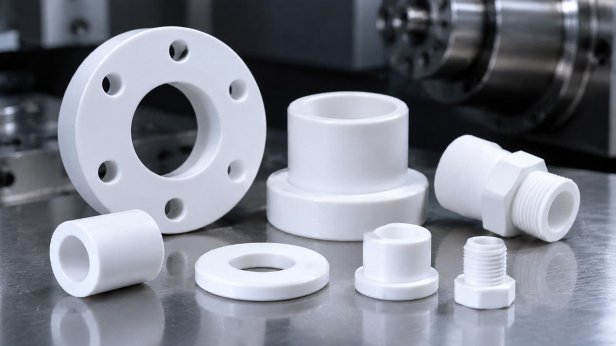

Three Core Principles for Achieving High-Precision PTFE Machined Parts:
With this engineering guide, you will gain an in-depth understanding of PTFE CNC machining techniques, PTFE material properties, precision machining tolerances, common defects (including creep, burrs, and warping), and expert solutions to overcome these challenges.
Case Study Overview
The end case study will show: To address the 25% defect rate involving tapered bore ovality and end-face warping in PTFE cryogenic valve seats previously supplied by another manufacturer, we optimized the clamping structure, introduced a staged machining process and stress-relief treatment, increasing the batch production yield to 99.4% and achieving a 100% pass rate in assembly leak-tightness tests.
Polytetrafluoroethylene (PTFE), a polymer of the tetrafluoroethylene monomer, is a thermoplastic plastic.
However, due to its high melting point of 327°C and exceptionally high melt viscosity, it cannot be processed using conventional injection molding. Instead, PTFE is primarily manufactured by compression molding and sintering billets or sheets, which are then machined using CNC cutting processes.
When working with this material, you will also commonly encounter its commercial name, Teflon (Teflon is a registered trademark of DuPont/Chemours).
For detailed physical property values of unmodified PTFE (Virgin PTFE), you can refer to our page: Custom PTFE (Teflon) CNC Machining Services, which provides a detailed material property table.
PTFE Material Grade Comparison: Filled vs. Virgin PTFE
Let’s look at the differences between various PTFE grades. Each grade has distinct properties that need to be considered and balanced during part design and material selection.
Virgin PTFE (Unfilled PTFE): The purest form of PTFE, suitable for applications requiring FDA food-grade and USP Class VI medical-grade compliance. It offers excellent electrical insulation and wear resistance but is the most susceptible to creep.
Mechanical Grade PTFE: Contains recycled PTFE material and is commonly used for cost-sensitive sealing and gasket applications.
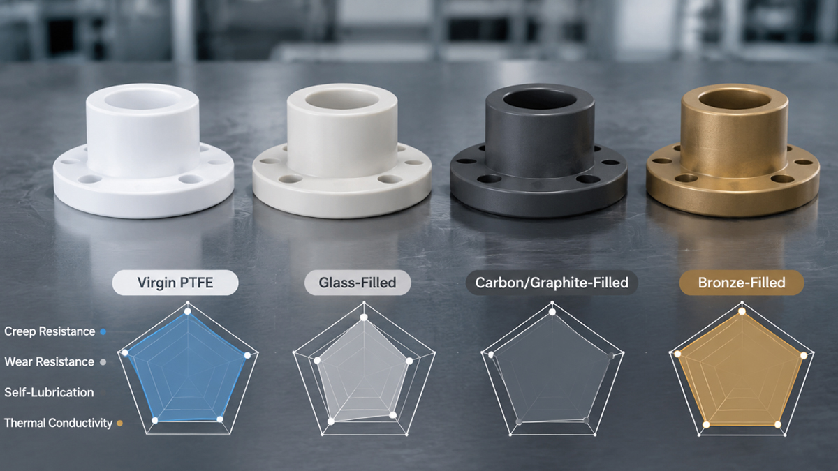
Filled PTFE (Modified PTFE):
The following are some of the practical questions most frequently raised by customer teams, including procurement professionals and design engineers, when our CNC machining factory receives custom PTFE CNC machining orders. We have summarized them here for quick reference.
Is PTFE easy to machine?
PTFE is soft and has a relatively low hardness (Shore D 50–65). Its cutting resistance is low, meaning it can be machined with relatively low spindle power. However, in terms of maintaining dimensional accuracy, PTFE is a challenging engineering plastic to machine.
Is PTFE machining expensive?
PTFE raw material costs are moderate to relatively high (higher than PP, PE, and ABS, but lower than PEEK and Torlon; see other common engineering plastics here). Although individual cutting operations can be completed quickly, high-precision parts often require additional deburring operations and multiple stress-relief annealing cycles, resulting in longer overall machining times.
Achievable Machining Tolerances:
Surface Roughness (Surface Finish):
In the previous sections, you learned about the properties of PTFE and its modified grades, as well as its machining characteristics. These material and machining properties make it possible to produce parts that meet both chemical purity and geometric precision requirements.
Below are some common industries and specific applications for CNC machined PTFE parts. Review these examples to see whether they match your current project requirements. If you are unsure whether PTFE is suitable for your components, feel free to consult our engineering team for material selection advice.
Semiconductor and Chemical Processing Industries:
Fluid Power and Valve Sealing:
Electrical and RF/Microwave Applications:
Medical and Life Sciences:
When your newly designed PTFE products need to be manufactured through CNC machining, you shoulf consider the potential risks of manufacturing defects. Even if you choose a qualified machining factory, the following situations may still occur:
Cause: PTFE has an extremely low elastic modulus and is highly susceptible to elastic deformation. If the fixture applies excessive clamping force, a hole may become oval after the part is released from the machine and springs back. During deep-hole drilling, the material may also be pushed radially by the cutting tool, causing the hole diameter to shrink after the tool is withdrawn, resulting in an undersized feature.
Recommendations for You: Avoid using structurally weak areas as primary locating datums in your drawings. Discuss specifying free-state tolerances with your machining supplier.
How Our Factory Addresses This Issue: To resolve or minimize these manufacturing risks, we use soft jaws, fully enclosed collet chucks, or vacuum fixtures. Before drilling, we may also leave finishing allowance or use stepped reaming to achieve the required hole dimensions.
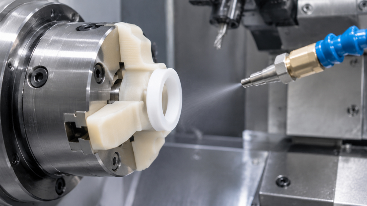
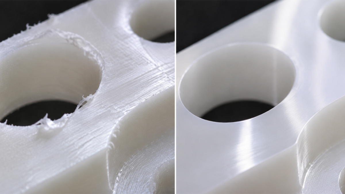
Cause: PTFE is highly tough and ductile. Instead of breaking into small chips during cutting, it tends to produce long, continuous, noodle-like chips. At hole edges, the material can also be pushed and deformed into soft, curled burrs.
Tips for You: Consider designing 0.2–0.5 mm chamfers or radii at feature edges to avoid sharp edges.
Our Solutions: We use polished fine-grain carbide tools with a high positive rake angle or single-crystal/PCD diamond tools. We can also program reverse chamfering toolpaths to improve edge quality. For deburring, cryogenic deburring may be used to remove unwanted material.
Engineering Mechanism: PTFE billets naturally contain residual stresses introduced during extrusion or sintering. Extensive pocketing or heavy material removal can disrupt the internal stress balance. As a result, a part may pass dimensional inspection in the workshop but develop bending or warping several days after shipment as internal stresses are gradually released.
Recommendations: Maintain symmetrical and uniform wall thickness wherever possible, and avoid large pockets on only one side of the part. For high-precision structural components, explicitly specify an annealing requirement after rough machining.
Our Factory’s Approach: We implement a machining sequence of rough machining, intermediate stress-relief annealing, and finish machining. A typical annealing process involves heating the part to 150°C–200°C in a temperature-controlled oven, holding it for several hours, and then allowing it to cool very slowly.
Why It Happens: Using slightly dull tools previously used for metal cutting, or running the spindle at excessively high speeds, can cause heat buildup beyond the material’s thermal limits. Under these conditions, the cutting tool stops cleanly shearing the material and instead begins tearing or dragging it.
Design Recommendations: Avoid blindly specifying metal-level mirror polishing requirements (such as Ra <0.2 µm) on PTFE drawings. Set reasonable surface finish requirements based on the actual functional needs of the sealing surfaces.How We Handle This: We use sharp cutting tools with polished flutes designed specifically for plastics. Cutting speeds are carefully controlled, while high-speed air blast or oil-free, water-soluble coolant can be used to remove heat. Excessive friction during dry cutting must be avoided.
Why This Happens: PTFE has a relatively soft surface. Contact with ordinary hard metal objects or collisions between individual parts can easily leave indentation marks. Damage to critical sealing surfaces may compromise sealing performance and lead to gas leakage.
Recommendations for You: When placing an order, clearly specify that critical sealing surfaces must be covered with protective film and establish an individual packaging agreement for each part.
Our Packaging Protection: We use dedicated trays for individual parts during production transfers. After cleaning, each component is separately protected using bubble bags, protective netting, or custom thermoformed plastic trays to prevent contact and impact damage.
Cause: When PTFE wall thickness is typically below 1.0 mm or the length-to-diameter ratio is excessively high, axial cutting forces can cause thin walls to deflect away from the cutting tool. This may result in uneven wall thickness or even tool breakthrough.
Design Recommendations: Follow DFM principles. For PTFE machined components, we recommend maintaining a minimum wall thickness of at least 1.5 mm and avoiding excessively thin sections at the bottoms of deep blind holes.
Our Factory’s Solutions: We use light depths of cut and fast feed rates. A backing mandrel is also used to support the inner surface of thin-walled components before machining their external surfaces.
Customer Challenge:
A fluid control equipment customer needed to purchase PTFE valve seats in batches for cryogenic applications. The required flatness of the sealing face was 0.02 mm, with a bore diameter tolerance of ±0.03 mm.
The first batch of samples previously sourced from another supplier passed dimensional inspection before shipment. However, during overseas assembly, approximately 25% of the parts were found to have ovalized tapered bores and warped end faces. This resulted in uneven sealing contact and inconsistent assembly performance.
To address the dimensional stability issues in batch production, the customer subsequently assigned the project to our team for evaluation.
Technical Root Cause Analysis:
We analyzed the part geometry, machining features, and material characteristics. Our assessment indicated that the issues were primarily related to PTFE’s viscoelastic behavior, residual machining stresses, and temperature variations.
The previous supplier’s machining process did not adequately control clamping deformation in the deep-hole areas. Excessive clamping force may have caused elastic recovery after the parts were released from the fixtures. In addition, insufficient stress relief after rough machining, combined with temperature fluctuations during long-distance ocean transportation, further increased the risk of internal stress release and dimensional changes.
Solutions from Our Engineering Team:
Improvement Results:
By optimizing the fixturing design, machining sequence, and quality verification process, we increased the batch production yield to 99.4%. The sealing performance test during assembly achieved a 100% pass rate.
These improvements resolved the batch dimensional deformation issues encountered with the previous supplier’s production process, improving PTFE valve seat assembly consistency and delivery reliability.
In summary, PTFE offers irreplaceable value in precision sealing components and semiconductor fluid handling parts thanks to its low coefficient of friction, wide operating temperature range, and excellent chemical inertness. However, its low rigidity, high creep tendency, large coefficient of thermal expansion, and significant elastic recovery also make it highly susceptible to burr formation and dimensional deformation during conventional cutting operations. Metal or ordinary plastic machining standards should never be directly applied to PTFE.
Overcoming these engineering challenges and ensuring dimensional stability in batch production requires a combination of precise material selection and process control. During the design stage, actual operating loads should be evaluated first. For high-wear or high-pressure applications, glass-filled or carbon-filled modified PTFE should be considered. During manufacturing, ultra-sharp specialized cutting tools, custom soft-jaw fixturing, and staged stress-relief annealing are essential to minimize batch production risks such as oval deformation and delayed warping.
For PTFE precision machining project issues involving deformation, tolerance control, material selection, or DFM evaluation of new drawings, feel free to send your requirements and drawings to our engineering team. We provide free engineering advice and prompt quotations for custom PTFE precision machining services. [We support 2D Drawings (PDF files), 3D Drawings (IGS/STP/STEP files)].
 WhatsApp/WeChat/Mobile:
+86-15099911516
 Tel: 86-150-9991-1516
 QQ: 939020977
 E-Mail: service@vimetal.com.cn


How Does 3D Printing PTFE Compare with CNC Machining?
PTFE 3D printing technology is still with challenges including high shrinkage rates (often reaching 15–25%), high internal porosity, and rough surface finishes. For industrial components such as seals and valve seats that require full material density and reliable sealing performance, CNC machining is currently the only proven manufacturing process capable of achieving surface finishes of Ra 0.4–1.6 µm and maintaining long-term dimensional stability.
Why Is CNC Machining Recommended Over Injection Molding for Precision PTFE Parts?
PTFE has extremely high viscosity in its molten state and cannot flow like conventional plastics. Therefore, it cannot be processed using standard injection molding. Although PTFE powder can be molded and sintered into blanks using specialized molds, high-precision features, such as those requiring ±0.025 mm tolerances, must be produced through CNC machining. CNC machining eliminates expensive mold costs while providing higher dimensional accuracy.
How Can PTFE Creep (Cold Flow) Be Reduced During Part Design?
How Do PTFE, PP, and PE Differ in Material Performance?
PTFE offers significantly better high-temperature resistance and chemical resistance than PP and PE. PP and PE are generally suitable for conventional operating environments below 80–100°C, whereas PTFE can withstand continuous operating temperatures of up to 260°C and resist most strong acids and alkalis. It also meets the UL 94 V-0 flame-retardancy classification, making it a preferred choice for high-performance material upgrades.
What Is PTFE Coating, and How Does It Differ from CNC Machined Parts?
They are two different things. PTFE coating involves spraying PTFE powder onto metal surfaces, such as cookware or rollers, to provide non-stick or corrosion-resistant properties. In contrast, CNC machined PTFE parts are structural components cut from solid PTFE rods.
When a component needs to withstand high loads, function as a precision sealing part, or maintain long-term chemical resistance, solid PTFE CNC machined parts should be used to avoid the risk of coating failure or peeling.
Why Is PTFE Suitable for Sealing, Corrosion-Resistant, and Lubrication Applications?
PTFE offers excellent chemical inertness, a wide operating temperature range (-200°C to +260°C), and an extremely low coefficient of friction. In addition, CNC machining can achieve surface finishes as fine as Ra 0.4 µm.
These properties make PTFE suitable for a wide range of applications, including corrosion-resistant fluid manifolds, valve seats, pump diaphragms, cryogenic seals, high-frequency insulators, and lubrication-free bushings.