The Ultimate Guide to Metal Prototyping: Processes, Materials, and Design Recommendations
By JunWen Liu | Sept. 21, 2026
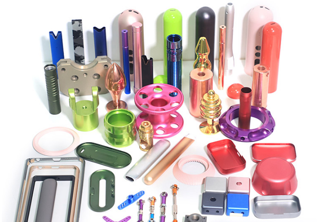

Metal prototyping is a cost-effective, small-batch manufacturing approach where you select metals or alloys that meet requirements for strength, corrosion resistance, fatigue resistance, or biocompatibility, and fabricate them into early-stage custom parts using CNC machining, metal 3D printing, sheet metal fabrication, or stamping. When design revisions or testing iterations are needed, these metal parts prototype can be reproduced quickly and economically.
But do you know how to choose the right metal for your prototype?
Which processes are available, and how should you evaluate them?
This article covers these core questions, along with essential cost and DFM (Design for Manufacturability) considerations, to help you achieve fast, high-quality, and cost-effective metal prototype manufacturing.
Finally, we share a case study showing how we helped a client evaluate processes, apply DFM Recommendations, CNC machine an aluminum optical barrel prototype, perform functional testing, and successfully move into full-scale production.
“Metal” is a broad umbrella term that encompasses raw, unrefined ores, commercially pure metals consisting primarily of a single element, and the vast array of engineered alloys widely used today.
Pure metals showcase their inherent properties in their most extreme form:
However, alloying these pure metals with other elements yields a wide variety of optimized mechanical properties tailored to specific applications:
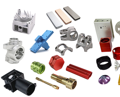
Below is a detailed comparison matrix to help you quickly evaluate and select the best material for your prototype:
(Or you may more detailed material specifications or specific metal grades for prototype manufacturing, just contact us for metal prototype materials selection.)
| Metal Materials | Alloy Grade | Key Properties | Machinability and Formability | Typical Applications | Relative Cost |
| Aluminum | Al 6061-T6 | Excellent corrosion resistance, good strength, highly versatile | Superior machinability, good formability | Structural components, enclosures, automotive and consumer parts | $ |
| Al 7075-T6 | Ultra-high strength-to-weight ratio, high hardness | Good machinability, low formability | Aerospace components, high-stress structural parts | $$ | |
| Brass | C36000 (Free-Cutting Brass) | High machinability, excellent wear and corrosion resistance | Industry gold standard for fast machining | Threaded fasteners, fittings, valves, gears | $$ |
| C26000 (Cartridge Brass) | High ductility, excellent cold-working and deep-drawing properties | Fair machinability, excellent cold formability | Stamped sheet metal parts, enclosures, radiator cores | $$ | |
| C46400 (Naval Brass) | Outstanding resistance to seawater and marine corrosion | Good machinability, fair cold formability | Marine hardware, underwater fittings, propeller shafts | $$$ | |
| Carbon Steel | 1018 (Low Carbon Steel) | Good weldability, uniform strength, highly economical | Excellent machinability, great cold forming | Shafts, pins, brackets, general structural prototypes | $ |
| 1045 (Medium Carbon Steel) | Higher strength and hardness, responds well to heat treatment | Fair machinability, moderate formability | Gears, axles, bolts, heavy-duty machinery parts | $ | |
| Stainless Steel | SS 304 / 304L | Excellent corrosion resistance, high toughness, good weldability | Moderate machinability, great formability | Medical housings, food-grade equipment, enclosures | $$ |
| SS 316 / 316L | Superior pitting resistance (marine and chemical environments) | Moderate machinability, good formability | Marine hardware, chemical equipment, medical devices | $$$ | |
| SS 17-4 PH | High strength, high hardness, exceptional corrosion resistance | Fair machinability (annealed state) | Aerospace valves, turbine blades, high-stress shafts | $$$$ | |
| Alloy Steel | 4140 (Chromoly) | Outstanding toughness, fatigue resistance, heat-treatable | Fair machinability, moderate formability | High-stress gears, shafts, crankshafts, automotive parts | $$ |
| 4340 | Exceptional strength, wear resistance, extreme fatigue limit | Challenging to machine, low formability | Heavy-duty aerospace shafts, landing gear components | $$$ | |
| Tool Steel | D2 | High carbon/chromium, extreme wear resistance and hardness | Low machinability (requires EDM/Grinding) | Stamping dies, cutting tools, wear plates | $$$ |
| Titanium | Ti-6Al-4V (Grade 5) | Extreme specific strength, biocompatible, high temperature tolerance | Difficult / Slow to machine | Medical implants, aerospace structural prototypes, marine tech | $$$$$ |
Please note that the mechanical properties and microstructures of these standard alloy grades apply exclusively to subtractive and cold-forming processes that preserve or slighly change the original raw material structure, such as CNC machining, sheet metal fabrication, and metal stamping.
Advanced powder-based additive manufacturing (e.g., DMLS or SLM metal 3D printing) uses other specialized metal powders that undergo full thermal melting and re-solidification, resulting in distinct material characteristics and grain structures.
Speed, precision, and cost efficiency are key to successful custom metal prototyping development. Explore how the right metal prototyping process can accelerate your design iterations and pave the way for batch production:
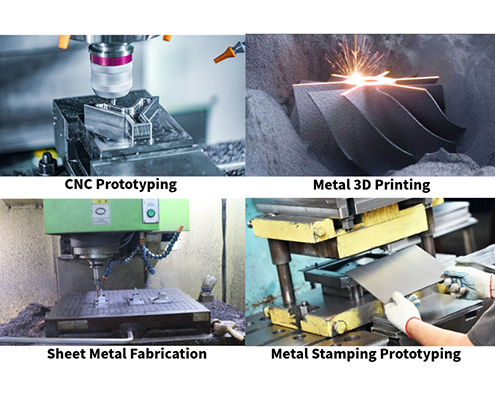
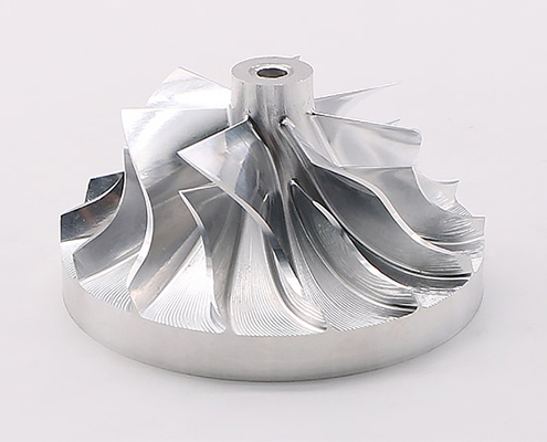
CNC machining is a subtractive process where high-speed cutting tools (mills, lathes) precisely carve away material from a solid metal block, rod, or sheet based on CAD file instructions. This prototyping way can achieve tight tolerances down to ±0.005 mm with superior surface finishes. It also uses mill-rolled engineering metals, ensuring prototypes share the exact mechanical and thermal properties of production parts. Another benefit is that you will need zero upfront mold or die tooling costs, enabling fast turnaround times within hours or days.
Cost Profile:
Moderate per-unit cost. Material waste is higher due to subtractive cutting (especially for hollow parts), and machining time directly dictates total cost.
Limitations:
DFM Design Recommendations:
CNC machining is frequently compared with metal 3D printing (DMLS/SLM). In practice, CNC machining remains the most common choice when parts require standard geometric shapes, ultra-tight tolerances, structural integrity, and native material properties without post-processing complexity.
However, rather than strictly competing, these two technologies often complement each other: you can choose 3D printing for highly complex internal geometries and then use CNC machining as a secondary post-processing step to achieve precise sealing faces, tapped threads, and strict dimensional tolerances.
In metal prototype manufacturing, DMLS and SLM 3D printing offer unmatched design flexibility, but their long-term production path differs significantly from CNC machining.
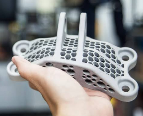
Direct Metal Laser Sintering (DMLS) and Selective Laser Melting (SLM) use a high-powered laser to selectively melt layers of fine micron-scale metal powder onto a build platform, constructing complex parts layer by layer from the ground up. Metal 3D printing excels at producing organic curved surfaces, internal conformal cooling channels, and lightweight lattice structures impossible with traditional tooling. It also merges multi-piece assemblies into a single printed metal component, removing assembly steps.
Cost Profile:
Higher prototype cost. Specialized metal powders are expensive, and post-processing (wire EDM platform removal, support structure clearance, and CNC touch-ups) adds significant labor and equipment expenses.
Limitations:
DFM Design Recommendations:
When a prototype is validated using CNC machining, the project almost always transitions into CNC machining for low-to-medium mass production because the material and process remain identical. Metal 3D printing works differently: because parts are formed by melting or sintering metal powders layer-by-layer, their internal grain structure, tensile strength, and fatigue resistance may not fully match those of forged or mill-rolled alloys.
When a 3D-printed metal prototype fails structural or fatigue testing, you can pivot to CNC machining using solid bar stock and a comparable alloy for production. Alternatively, if a 3D-printed prototype passes testing and the project scales to high volumes (10,000+ units), and the as-printed surface roughness (similar to sand casting) is acceptable, your team can choose other ways such as metal investment casting or die casting using casting alloys, which significantly reduces unit costs while often keeping the castings’ strength.
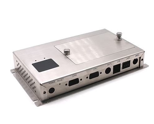
Sheet metal fabrication is the process of flat metal sheets of uniform thickness are laser-cut or punched into flat patterns, then formed into 3D shapes using CNC press brakes. Multiple components are joined using TIG/MIG welding, press-fit hardware (PEM studs), or mechanical fasteners. This method is ideal for structural enclosures, mounting brackets, chassis, and thin-walled housings. The efficient flat nesting reduces material waste, leading to rapid lead times.
Cost Profile:
Highly economical for low-to-medium volume prototypes. Requires no expensive hard tooling—only digital programming for cutting and bending.
Limitations:
DFM Design Recommendations:
Metal prototypes produced through sheet metal fabrication are often also subject to heat treatment and welding.
When multi-part sheet metal enclosures or heavy brackets require extensive TIG/MIG welding, localized heat inputs can introduce significant internal stress and thermal distortion. To counteract this and restore material ductility, prototypes may undergo localized or full heat treatment (such as stress-relief annealing) prior to final inspection. Additionally, post-weld operations like grinding, surface passivation, or powder coating are standard steps to conceal weld seams and prevent corrosion along heat-affected zones (HAZ).
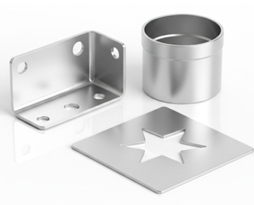
Prototype stamping utilizes soft tooling, modular dies, or prototype presses to stamp, draw, form, and bend sheet metal into complex shapes under high pressure in a single or sequential stroke. It validates material stretchability, drawability, and springback characteristics prior to committing to full production tooling. The stamping also efficiently manufactures complex 3D contoured sheet metal parts (e.g., automotive body panels, drawn shields).
Cost Profile:
Highest initial investment among prototyping methods. While soft tooling is cheaper than production hard tooling, the upfront mold creation drives up initial costs.
Limitations:
DFM Design Rules:
While metal stamping is technically part of the broader metal fabrication family, it is typically treated as a distinct process when compared to traditional sheet metal fabrication.
The primary difference lies in how complex 3D shapes and curved surfaces are produced. Traditional sheet metal fabrication relies on cutting flat sheets and making linear bends using press brakes, making it ideal for low volumes with zero tooling costs. Prototype metal stamping, on the other hand, uses custom soft-tooling dies to form complex, non-linear 3D contours and deep-drawn shapes in a single stroke. While stamping carries higher upfront tooling expenses, it serves as the ultimate validation step for projects transitioning to high-volume, automated stamping production.
Every prototyping method balances speed, precision, and cost differently. Use the reference matrix below to quickly identify which process aligns best with your design requirements and test quantities.
| Comparison Attribute | CNC Machining | Metal 3D Printing (DMLS / SLM) | Sheet Metal Fabrication | Metal Stamping Prototyping |
| Primary Applications | High-precision, structured parts requiring native material properties | Highly complex/organic geometries, conformal channels, lightweight lattice parts | Thin-walled components, enclosures, brackets, structural housings | Complex 3D contoured sheet parts used for mass production validation |
| Dimensional Tolerance | Extreme (±0.005 mm) | Moderate (±0.1 mm) | Moderate (±0.2 mm) | High (±0.05 mm) |
| Surface Finish | Superior (Ra 0.8–3.2 µm) | Rough / Gritty (Ra 6.3–12.5 µm, similar to sand casting) | Good (Depends on raw sheet finish & post-processing) | Good (Smooth drawn or formed finish) |
| Geometric Freedom | Moderate (Limited by tool access and internal sharp corners) | Extreme (Virtually unrestricted internal/external geometry) | Low (Restricted to uniform wall thickness and linear bends) | Moderate (Restricted by material draw limits and draft angles) |
| Initial Setup & Tooling Cost | Low (Setup & Programming Fee) Zero molds; covers CAM programming, custom fixtures, and alignment | Very Low (File Prep Fee) Zero tooling; covers CAD slicing, build prep, and powder setup | Low (Setup & Programming Fee) Uses standard tooling; covers nesting, programming, and brake setup | Moderate to High (Soft Tooling Fee) Requires dedicated prototype soft dies or modular die setups |
| Per-Unit Cost Profile | Moderate (Driven by machine runtime and material waste) | High (Driven by metal powder cost and post-processing) | Low (Highly economical for flat-pattern nesting) | Decreases significantly as order volume increases |
| Material Scrap Rate | High (Subtractive cutting) | Low (Additive process; excess powder is recycled) | Very Low (Optimized nesting layout) | Low (Sheet blanking waste only) |
| Production Lead Time | Fast (1–3 days) | Fast (2–5 days) | Fast (2–4 days) | Moderate (1–2 weeks for soft tool machining) |
| Recommended Test Quantity | 1 – 50 pcs | 1 – 10 pcs | 1 – 100 pcs | 50 – 1,000 pcs (Pilot Run / PVT) |
| Production Transition Path | Continues with CNC machining or scales up to metal casting | Continues with 3D printing, or pivots to MIM / metal casting | Continues with sheet metal or transitions to hard-tool stamping | Direct seamless transition to high-volume hard-tool stamping |
From CAD Model to Batch Production of an Aluminum Optical Barrel Prototype
When a precision optical instrument company approached us with a high-precision optical barrel design, they faced a critical manufacturing challenge. The component required strict concentricity, tight internal tolerances to align multiple lens elements, and absolute structural stability under temperature variations. The client initially asked whether metal 3D printing could be used to manufacture the prototype. We analyzed the tradeoffs for them: while 3D printing offered geometric flexibility, using Aluminum 6061-T6 by 5-axis CNC machining was the superior choice to guarantee native material strength, avoid internal micro-porosity, and achieve the exact dimensional accuracy required for optical alignment.
During the Design for Manufacturability (DFM) review, our engineers identified several areas for cost optimization and presented a formal engineering change proposal. We recommended adjusting the deep internal fillet radii to match standard cutting tool dimensions and modifying non-critical wall thickness transitions to cancel unnecessary multi-axis re-orientations. Upon review, the client approved the reasonable DFM modifications. These engineering tweaks were localized to internal non-optical faces, ensuring zero compromise on the part’s external aesthetic appearance, structural integrity, or optical alignment performance. By removing expensive custom tooling and reducing overall machine cycle time by 15%, the DFM modifications yielded an 17% reduction in total manufacturing costs per unit.
Using our advanced 5-axis CNC machining centers, we manufactured an initial batch of ten aluminum optical barrel prototypes within 6 working days. The raw aluminum components underwent precision turning, thread milling, and a black hard-coat anodizing finish to minimize internal light reflection. Once delivered, the client performed rigorous functional testing, including lens assembly fit, thermal expansion evaluations, and stray-light optical testing. With the prototype design fully validated using authentic production-grade material, the transition to full-scale production was effective and smooth. The project successfully produced from the initial ten-piece prototype run to a recurring production batch of 2,000 units, delivering high-precision optical barrels on time while maintaining maximum cost efficiency.
This guide has covered the material properties and selection recommendations for metal prototyping, as well as the primary metal prototyping processes (CNC machining, metal 3D printing, sheet metal fabrication, and metal stamping) alongside their cost profiles and key DFM guidelines.
Selecting the optimal metal material and manufacturing process requires balancing several project trade-offs—including part geometric complexity, dimensional accuracy, mechanical performance requirements, and testing quantities:
Are you currently facing challenges with process selection, struggling with high unit machining costs, or looking to mitigate design risks before tooling up? Feel free to reach out to us, and send us your drawings to receive a fast, detailed quote alongside a practical Design for Manufacturability (DFM) review from our engineering team. Let’s optimize your parts for performance and cost before production begins.[2D Drawings (PDF files), 3D Drawings (IGS/STP/STEP files)].
 WhatsApp/WeChat/Mobile:
+86-15099911516
WhatsApp/WeChat/Mobile:
+86-15099911516 Tel: 86-150-9991-1516
 QQ: 939020977
 E-Mail: service@vimetal.com.cn


How do secondary surface finishes affect the final dimensions of metal prototypes?
Finishes like bead blasting have virtually no impact on dimensions, but functional coatings add measurable thickness. For instance, Type III hard-coat anodizing typically adds 12-25 μm per side. Critical mating faces, precision bearing seats, and thread pitches must factor in these coating allowances during the initial CAD design and CNC programming.
How are internal threads and sealing faces protected during anodizing or welding?
To keep functional areas clean, engineers use dedicated masking methods before secondary operations. High-temperature silicone plugs, custom caps, or temporary screws are fitted into threaded holes and sealing surfaces prior to anodizing, powder coating, or plating. This prevents material buildup and avoids the need for secondary re-tapping.
Is it common to combine different manufacturing processes in a single prototype assembly?
Yes, most complex products use hybrid manufacturing. A structural metal enclosure might use sheet metal fabrication for the main body, CNC-lathed brass standoffs for internal mounting, and a 3D-printed metal bracket for complex cable routing. Managing tolerances across all components ensures everything fits together cleanly during final assembly.
How does thermal expansion influence material selection for metal parts?
Metals expand and contract at different rates under temperature changes. For example, aluminum has a higher coefficient of thermal expansion (CTE) than stainless steel or titanium. If your prototype operates in high-temperature environments or mates with dissimilar metals, these expansion rates must be built into the part tolerances to prevent binding, leakage, or structural warping.
What inspection reports and quality documentation can be provided with prototypes?
Depending on testing and industry needs, prototypes can be supplied with complete documentation. Common options include Material Test Reports (MTRs) confirming chemical composition, CMM Inspection Reports for critical dimensions, First Article Inspection (FAI) documentation, and basic Certificates of Conformance (CoC).


 Top 10 Rapid Prototyping Companies in China (2026 Guide)