How Long Does It Take to Make a Prototype? Full Timeline, Hidden Delays, and Acceleration Tips
By JunWen Liu | Sept. 26, 2026
It’s a big challenge that the misalignment between your estimated prototyping schedule and the actual timeline will lead to project delays and missed product launch dates. Even if you check time estimates from other websites, service providers, or this guide itself, it is always best to buffer in a few extra weeks. Turning a 3D CAD drawing into a physical sample actually doesn’t take much time. Depending on the manufacturing process, it can take anywhere from a few days to a couple of weeks.
However, you cannot overlook the additional time required for initial design and drafting, functional testing, multi-round design iterations, as well as internal communication, vendor alignment, and logistics. Because of these factors, the entire lifecycle can take anywhere from several weeks to up to a year, depending on product complexity, manufacturing processes, design maturity, and even regulatory approvals for specialized products.
In this article, you will learn about the full timeline, hidden delays, and acceleration tips for your prototype making. At the end, we will also share a case study of how we overcame machining challenges to deliver precision aluminum earphone cases with 0.02 mm tolerance in 10 days.
As mentioned earlier, bringing a prototype to life typically covers five major phases:
Prototyping Development Phases and Estimated Lead Times
| Development Phase | Estimated Time | Overview |
| 1. From Idea to Sketch to CAD Model | 3 Days – 3 Weeks | Conceptual sketching, 3D modeling, and creating functional CAD files ready for engineering evaluation. |
| 2. Rapid Prototyping Processing (Incl. Material Selection & DFM Feedback) | 1 – 4 Weeks | Depends on the selected manufacturing process (detailed in the following section). |
| 3. Surface Finishing & Secondary Operations (Optional) | 2 Days – 1 Week | Bead blasting, anodizing, painting, electroplating, heat treatment, or sub-assembly, depending on surface requirements. |
| 4. Design Iterations and CAD Revisions | 3 Days– 2 Weeks (Per Iteration) | Physical part inspection, functional testing, engineering reviews, and updating 3D CAD models based on test results. |
| 5. Cumulative Lifecycle Until Final Approval | 4 – 12 Weeks+ (Total Project Time) | Most complex hardware products require 2 to 4 iteration loops before reaching a production-ready design. |
Selecting the right rapid prototyping method is a crucial link in this chain. It depends heavily on your testing objectives, batch volume, and budget. Crucially, it also dictates the production turnaround time.
For a single production run, here is how long each process typically takes:
Keep in mind that the lead times listed above cover only a single production run. Real-world prototype development involves visual models, various functional tests, and multiple iteration loops, which altogether typically require 4 to 12 weeks.
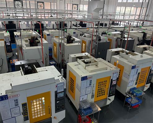
Even after learning the lead time for a single production run, it is clear that prototyping is rarely a one-and-done process before market launch. However, in this multi-round iteration lifecycle, the total time required is not simply the sum of individual manufacturing cycles. There are several hidden time costs that must be factored in and managed effectively:
Your internal team will need dedicated time to discuss design revisions, process budget approvals, align on product specifications, such as color, material grade, tolerances, and surface finish, and map out project schedule.
When reaching out to rapid prototyping providers, executing Non-Disclosure Agreements (NDAs) prior to sharing proprietary CAD drawings takes time. Once formal collaboration begins, working through Design for Manufacturability (DFM) reviews also requires back-and-forth alignment to resolve manufacturability issues, such as deep narrow pockets, sharp internal corners, or tight tolerances.
Actually, it’s barely that a prototyping vendor owns a complete suite of equipment spanning all manufacturing disciplines (such as 3D printers, CNC machinery, injection molding presses, welding setups, various surface finishing lines, heat treatment furnaces, and die-casting machinery). Most vendors specialize in some of these technologies. For custom prototypes that require specialized secondary operations or other processing, the parts are often outsourced to cooperated suppliers, which typically adds several days of transit and queue times.
First, managing internal communication and review timelines relies on your team’s workflow and management, and this is what I can’t help with.
Second, for external communication, it is best to partner with a responsive prototyping supplier that offers fluent technical communication and features an experienced engineering team capable of solving complex design challenges.
Finally, and most critically, it is recommended that you select a prototyping company located in an industrial cluster, such as those in Shenzhen, Zhongshan, or Dongguan. These locations are in close proximity to one another, benefit from supportive policies, and belong to an innovation-encouraging zone densely populated with various manufacturing plants. Most of them have long-term supporting partnerships with one another, making logistics and communication exceptionally fast while offering a broad range of available services.
When it comes to bringing a concept to life or making substantial design revisions, engineers in the manufacturing factory generally do not have the time to draft 3D CAD models for you. Their primary focus during the design phase is limited to supporting minor modifications that optimize the part for faster machining and lower production costs. Therefore, it is always best for your product development team to have in-house design engineers to create and modify drawings. When there’s no dedicated internal personnel, you can consider finding a specialized third-party engineering design firm.
Relying entirely on a prototyping manufacturer to handle full-scale drawing creation or major revisions will certainly delay your project. While they provide valuable Design for Manufacturability (DFM) feedback and may occasionally handle small, quick adjustments when bandwidth permits, design work falls outside their core operational scope. Reputable suppliers stay busy with active production runs, meaning CAD drafting takes a backseat. For the goal that moving quickly from concept to physical prototype, you may need have a reasonable expectation or plan for the drawing design work.
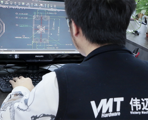
One of the most effective ways to shave days, or even weeks, off a product development schedule is to choose a best-fit prototyping manufacturer. While many facilities offer similar machining capabilities, their operational efficiency, supply chain network, and engineering responsiveness make all the difference in practical turnaround times.
To minimize lead times without compromising part quality, look for a prototyping partner that meets the following criteria:
In-House Machinery and Comprehensive Capability: Partner with suppliers that own and operate a diverse fleet of core equipment, such as multi-axis CNC mills, 3D printers, and standard post-processing tools. Minimizing reliance on third-party shops keeps primary fabrication processes under one roof and eliminates unnecessary handling delays.
One-Stop Service Integration: Work with a full-service provider that manages the entire workflow, from initial raw material sourcing to secondary operations like surface finishing, heat treatment, and sub-assembly, streamlines overall project management. Your team can work with one supplier instead of communicating with multiple vendors.
Strategic Location in an Industrial Cluster: Choose a partner based in a major manufacturing hub, such as Shenzhen, Dongguan, or Zhongshan. High supply chain density allows for rapid local sourcing of specialized raw materials, quick turnaround on outsourced secondary processes, and faster local transit times.
Responsive Communication and Rapid DFM Feedback: Work with a vendor that provides quick engineering reviews and clear, actionable Design for Manufacturability (DFM) feedback. Fast technical alignment during the quoting and CAD verification stage prevents costly production holds later in the process.
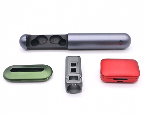
How We Overcame Machining Challenges to Deliver Precision Aluminum Earphone Cases with 0.02 mm Tolerance in 10 Days
A well-known audio brand required custom aluminum earphone charger cases for a new premium product line. The design featured a sleek, thin-walled enclosure with ultra-tight tolerance requirements to accommodate delicate internal electronics, magnetic closure mechanisms, and seamless hinge assembly. Initial test runs with previous suppliers suffered from part deformation due to thin wall thickness, as well as cosmetic defects on the exterior surface during machining, slowing down the project’s strict launch deadline.
Upon reviewing the 3D CAD files, our engineering team conducted a comprehensive Design for Manufacturability (DFM) analysis. The primary root causes of part warping were identified as residual stress from standard machining passes and uneven clamping force on thin-walled sections. To solve these issues without compromising the aesthetic or structural integrity of the design, our team developed a customized manufacturing plan. The strategy combined multi-axis CNC milling, specialized custom fixtures to distribute clamping pressure evenly, and optimized tool paths to reduce heat accumulation and material stress.
Production began with certified 6061-T6 aluminum block stock, which underwent incoming material verification via spectrometer testing to confirm composition and structure stability. Using high-precision 5-axis CNC machines, the shop floor executed a multi-pass roughing and finishing strategy with strict spindle speed and feed rate controls, allowing internal stress relief between operations. Custom soft jaws were engineered specifically to support the delicate thin-walled enclosure during high-speed internal pocketing, eliminating tool chatter and preventing wall crushing. Following machining, the parts passed CMM dimensional inspection before undergoing precision automated bead blasting to uniform the surface texture, completed by a strict temperature-controlled anodizing process to yield a flawless, corrosion-resistant matte finish that met the client’s premium cosmetic standards.
By refining the clamping strategy and optimizing machining parameters, the total production cycle was kept within a strict 10-day turnaround for the prototype batch. The final aluminum earphone cases achieved total compliance with tolerance specifications (±0.02 mm), zero wall deformation, and a flawless anodized surface finish. The client was extremely satisfied with the exceptional quality and fast delivery, allowing them to proceed smoothly with assembly testing and confidently award us their subsequent production orders.
Determining how long it takes to make a prototype goes far beyond calculating machine run-times. While individual production processes like 3D printing or CNC machining can be executed in just 3 to 7 days, a complete prototyping lifecycle, spanning initial CAD modeling, DFM evaluations, surface finishing, and multi-round iterative testing, typically requires 4 to 12 weeks. Unseen issues such as internal team alignment, complex technical communications, sub-tier outsourcing, and drawing modifications play a massive role in the final delivery date. To fast-track prototype development timeline without sacrificing part accuracy, your product teams should manage internal design strictly, buffer in additional time for iterative testing, and partner with a well-equipped, responsive manufacturer situated within a major industrial cluster. Ready to turn your 3D drawings into high-precision physical parts without costly project delays? Upload your drawings today to receive a free Design for Manufacturability (DFM) analysis and an fast, competitive quote. [2D Drawings (PDF files), 3D Drawings (IGS/STP/STEP files)].
 WhatsApp/WeChat/Mobile:
+86-15099911516
WhatsApp/WeChat/Mobile:
+86-15099911516 Tel: 86-150-9991-1516
 QQ: 939020977
 E-Mail: service@vimetal.com.cn


What is the fastest prototyping process for functional metal parts?
CNC machining is typically the fastest process for high-strength, functional metal prototypes, offering turnaround times of 3 to 7 days for simple to moderately complex designs. For highly complex internal geometries that cannot be machined, metal 3D printing (DMLS/SLM) offers rapid fabrication within a similar timeframe.
How many design iteration rounds should I plan for in my prototype schedule?
Most hardware products require 2 to 3 iteration cycles before reaching a production-ready design. It is recommended to allocate 1 to 2 weeks per iteration loop to account for functional testing, design revisions, and secondary production runs.
Why does post-processing and surface finishing add extra lead time?
Secondary operations such as anodizing, powder coating, electroplating, or heat treatment require specialized equipment and precise chemical processes. If these operations are handled off-site or outsourced to specialized sub-tier vendors, transport and queue times can add 3 to 7 business days to your overall timeline.
Can a prototype factory create my 3D CAD drawings from scratch?
Generally, no. Manufacturing engineers focus primarily on Design for Manufacturability (DFM) reviews to optimize existing drawings for machining and cost efficiency. For full CAD generation or major structural redesigns, it is best to utilize in-house design engineers or hire a dedicated third-party product design firm.
How does a manufacturer’s geographic location impact my project lead time?
Suppliers located within major industrial manufacturing hubs (such as Shenzhen, Dongguan, or Zhongshan) benefit from dense supply chain networks. They can source specialized raw materials and access secondary processing services locally, significantly reducing logistics turnaround compared to isolated facilities.
How can I speed up the initial quoting and DFM review phase?
You can accelerate the upfront evaluation stage by providing complete 2D engineering drawings (with clear tolerance specifications, thread callouts, and surface finish requirements) alongside your 3D CAD files, and by signing NDAs promptly prior to submission.


 CNC Robotics: Role and Benefits in Automated CNC Machining