Complete Guide to Plastic Prototyping: Process Selection, Material Matching, and Cost Optimization
By JunWen Liu | Sept. 18, 2026
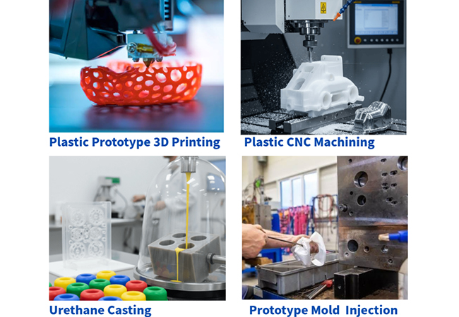

Plastic prototype manufacturing benefits significantly from the wide variety and relatively low cost of plastic prototypes. Whether you are developing visual prototypes or functional models, you can find highly cost-effective solutions to reduce trial-and-error costs. The extensive selection of plastics covers a broad spectrum of design requirements, including varying degrees of transparency, flexibility, rigidity, and mechanical strength. Meanwhile, plastic prototype manufacturing processes, ranging from 3D printing and CNC machining to prototype plastic injection molding and vacuum casting (urethane casting), offer distinct advantages, such as rapid prototyping and iteration, high precision, exceptional surface finish, low unit cost in volume, and realistic functional simulation.
Read this comprehensive engineering guide to plastic prototyping to master manufacturing techniques, material selection, cost optimization, and design-for-manufacturability (DFM) best practices for your plastic prototype parts. At the end of the article, we also share a case study from our factory: manufacturing a medical device housing using medical-grade PEEK via CNC machining, achieving a surface finish of Ra 0.4 µm and dimensional tolerances within ±0.02 mm.
Before selecting the suitable manufacturing process for plastic prototypes, a comprehensive evaluation is required based on project stage, part quantity, precision requirements, aesthetic/surface finishing needs, and budget. Here is a quick decision guide for four major plastic prototype manufacturing technologies, along with a comparative table covering accuracy, cost, lead time, and compatible materials:
| Process Type | Typical Accuracy | Cost Level | Lead Time | Compatible Plastic Materials |
| 3D Printing (SLA) | ±0.05 – ±0.1 mm | Low – Medium (per piece) | 1 – 3 days | Photosensitive resins (can simulate properties of ABS, PP, and optical PMMA) |
| 3D Printing (FDM) | ±0.2 – ±0.3 mm | Very Low | 1 – 2 days | PLA, ABS, PETG, TPU, Nylon (Filaments) |
| 3D Printing (SLS) | ±0.1 – ±0.2 mm | Medium | 2 – 4 days | PA12 Nylon, PA12+GF, TPU flexible powders |
| CNC Plastic Machining | ±0.01 – ±0.05 mm | Medium – High (per piece) | 3 – 5 days | Solid blocks/sheets of ABS, PC, POM, PEEK, PMMA, Nylon, PTFE, PBT, etc. |
| Vacuum Casting (Urethane) | ±0.15 – ±0.2 mm | Low – Medium (low-volume) | 5 – 9 days | PU Resins (precisely simulates ABS, PC, PMMA, PA, and silicone elastomers) |
| Plastic Molding Rapid Prototyping | ±0.02 – ±0.05 mm | High (includes initial tooling) | 10 – 20 days | Virtually all thermoplastics (ABS, PC, PA66, PEEK, TPE, LCP, etc.) |
To quickly understand how these processes work, browse the overview below. Combined with the advantages and quick decision rules mentioned above, this information allows you to make an initial match between a plastic prototyping material/process and your project requirements. However, there are also trade-offs to weigh to determine whether they are acceptable for your application:
Manufacturing a plastic visual prototype requires determining the level of surface finish, cost, and lead time based on your target audience. Of course, your design team must also carefully consider initial concepts for your plastic visual prototype, such as its overall aesthetic, color, texture, gloss level, and transparency.

Below are several common scenarios and recommended solutions for your reference:
| Visual and Aesthetic Need | Recommended Process | Recommended Material | Material Characteristics |
| Standard Matte / Painted Enclosure | CNC / Vacuum Casting / SLA | ABS (CNC) / ABS-like Resin (SLA) | Easy to sand, paint, and electroplate; the top choice for most electronic device housings. |
| High Transparency / Glass-like Finish | CNC / SLA | PMMA (Acrylic – CNC) / Clear Resin (SLA) | PMMA achieves exceptionally high optical clarity after polishing; clear resin suits complex geometries but may yellow over time. |
| Semi-transparent / Frosted Effect | CNC / SLA | PC (CNC) / Semi-transparent Resin | Offers unique light-diffusing effects, commonly used for lighting fixtures and indicator light guides. |
| Soft Touch / Rubber-like Feel | Vacuum Casting / 3D Printing | PU Elastomer (Vacuum Casting) / Rubber-like Resin (SLA/PolyJet) | Used to simulate phone cases, grips, seals, and overmolding effects. |
| Metallic Texture (via Post-processing) | CNC | ABS / PC | Non-metallic base materials with stable properties ideal for vacuum electroplating or metallic spray painting. |
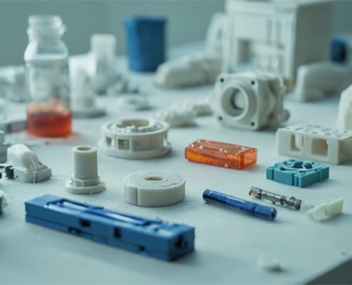
For functional plastic prototypes, the most critical step is clearly defining the real-world operating environment your prototype must withstand (including mechanical stress, temperature ranges, chemical exposure, and aesthetic requirements) before matching the materials and manufacturing processes. Once you have identified a compatible combination, you can refer back to the first section of this article to verify if it aligns with your precision and lead time constraints.
Below are process and material recommendations based on the primary core requirements of plastic functional prototypes:
| Primary Core Requirement | Recommended Process | Recommended Material |
| High Strength / Structural Load-Bearing | FDM, SLS, CNC Machining | Carbon Fiber-Filled Nylon (PA+CF), Neat Nylon (PA12/PA11), POM (Acetal/Delrin), PC |
| High Temperature Resistance (>100°C) | FDM, CNC Machining, Specialized SLA | PEEK, PEI (Ultem), PC, High-Temp Photosensitive Resin |
| High Dimensional Accuracy and Assembly Fits | CNC Machining, SLA, PolyJet | ABS, PC, PMMA (Acrylic), Standard Photosensitive Resin |
| Flexibility / Snap Fits / High Toughness | SLS, FDM, Injection Molding | TPU (Thermoplastic Polyurethane), PP (Polypropylene), Nylon |
| Optical Clarity / Transparency | CNC Machining, SLA | PMMA (Acrylic), PC, High-Clarity Photosensitive Resin |
In certain manufacturing scenarios, or due to cost and material property constraints, specific materials are not suitable for plastic prototype manufacturing. For example:
Thermosetting Plastics in 3D Printing and Plastic Molding Rapid Prototyping:
Materials like epoxy resins, phenolic resins, and certain rigid polyurethane formulations are not recommended for these processes. Once heat-cured, thermosets form an irreversible cross-linked molecular structure and cannot be remelted. Consequently, they cannot be reheated or reshaped if a molding error occurs or if design modifications are needed.
Hard-to-Machine and Hard-to-Bond Materials in CNC Machining:
Plastics such as Polypropylene (PP) and Polyethylene (PE) are poorly suited for rapid prototyping via CNC machining. Due to their high volumetric shrinkage rates (up to 1.5%–5%), these materials easily warp and deform during machining, making tight tolerances exceptionally difficult to achieve.
High-Cost Specialty Engineering Plastics in Early Prototypes:
From a cost perspective, unless there is a strict functional requirement, most early-stage prototype validations do not require expensive high-performance engineering plastics (such as PEEK or PI).
During plastic prototype development, mastering Design for Manufacturability (DFM) helps your engineering team identify major design risks and defects early. Implementing targeted design optimizations reduces trial-and-error costs, accelerates prototype iterations, and streamlines product development. The table below outlines design rules and pitfall-prevention tips for key plastic prototype manufacturing processes:
| Prototype Process | Recommended Min. Wall Thickness | Key Geometric Restrictions | Major Risks & Defects | Optimization Design Tips (DFM) |
| 3D Printing (SLA) | 0.6 – 0.8 mm | Overhangs > 19° require supports; deep enclosed blind holes trap resin. | Deformation if too thin, residual uncured resin, support mark blemishes. | Design drain/vent holes; add 45° chamfers to overhangs to minimize supports. |
| 3D Printing (FDM) | 1.0 – 1.2 mm | Noticeable Z-axis anisotropy; fine threads and small holes distort easily. | Interlayer cracking, bridge sagging, bottom edge warping. | Avoid placing primary load directions along the Z-axis; use brass heat-set/molded-in inserts for load-bearing threads. |
| 3D Printing (SLS) | 0.8 – 1.0 mm | No support structures needed; large flat surfaces warp easily due to heat buildup. | Thermal stress warping on flat areas, holes clogged by trapped powder. | Add ribs to large flat areas to prevent warping; include ≥2mm powder removal holes for enclosed cavities. |
| CNC Plastic Machining | 1.0 – 1.5 mm | Internal corners require tool radius (R); cavity depth should not exceed 4x tool diameter. | Thin walls deform from cutting heat, deep slot corners hard to clear, localized stress concentrations. | Add radii or relief slots (dog-bone corners) to internal corners; maintain uniform wall thickness to resist cutting forces. |
| Vacuum Casting (Urethane) | 1.5 – 2.0 mm | Abrupt wall thickness changes cause uneven shrinkage; excessive undercuts degrade silicone molds. | Shrinkage voids/bubbles, demolding tears, sink marks from uneven wall thickness. | Ensure smooth wall thickness transitions; leverage silicone elasticity for minor undercuts, and use block inserts for deep undercuts. |
| Plastic Injection Prototyping | 1.5 – 3.0 mm (varies by material) | Must design 0.5°–2° draft angles; strictly avoid unresolved undercuts. | Sink marks, weld lines, air traps, ejector pin marks/damage. | Follow uniform wall thickness rules (rib thickness ≤ 60% of nominal wall); design proper draft angles and parting lines. |
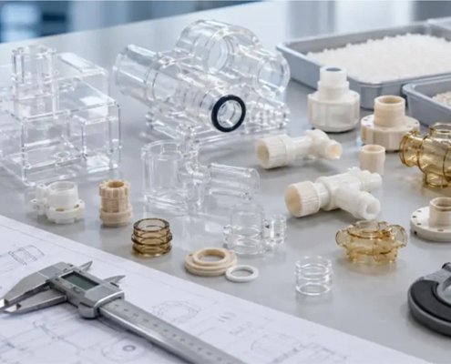
In plastic prototype development, controlling costs does not mean sacrificing quality or reducing precision. Instead, it involves finding the best strategy for material properties and manufacturing processes at different product development stages. A well-designed cost optimization strategy enables your team to achieve rapid sample iterations and validate market demand within a reasonable budget.
3D printing (SLA/FDM) or single-piece CNC machining should be your top choices. With zero tooling costs, pricing is based solely on single-piece labor and materials, allowing you to rapidly validate aesthetics, form, and basic fit dimensions with minimal upfront capital investment.
At this stage, the marginal cost reduction of 3D printing slows down, while steel molds remain cost-prohibitive. Vacuum Casting (Urethane Casting) is the most cost-effective option for this quantity range. Using a high-precision silicone mold (with a mold life of approximately 15–20 parts per set), you can rapidly and cost-effectively replicate polyurethane prototypes with highly representative physical properties.
Single-piece costs for CNC machining and vacuum casting hit a bottleneck. At this point, you should transition to Prototype Mold Plastic Injection. Utilizing aluminum alloy molds or unhardened soft steel molds requires an initial tooling investment, but as production volume increases, the unit cost decreases significantly through amortized tooling expenses, yielding plastic parts that match production-level quality.
Surface finishing for plastic prototypes determines not only visual and tactile texture, but also significantly enhances wear resistance, UV resistance, electrical insulation, and conductivity. Post-processing requirements generally fall into two primary categories: Visual Testing Models and Functional Testing Models. The former focuses on color accuracy, gloss levels, and flawless textures, while the latter prioritizes wear resistance, surface hardness, sealing performance, and corrosion resistance.
To help you select the most suitable post-processing solution efficiently, refer to the selection guide table below:
| Surface Finishing Process | Applicable Plastic Types | Core Treatment Effect | Visual Presentation Need (Visual) | Functional Testing Need (Functional) |
| Painting / Spraying | SLA Resin, ABS, PC, POM, Nylon | Restores custom Pantone colors, masks tool marks and layer lines. | Top Choice: Perfectly replicates production texture and color. | Optional: Enhances UV resistance and scratch resistance. |
| Polishing / Vapor Polishing | PMMA (Acrylic), PC, ABS | Eliminates microscopic surface roughness to achieve high light transparency. | Top Choice: High-clarity light covers and optical lens panels. | Essential: Reduces fluid resistance or improves sealing contact surfaces. |
| Screen Printing / Pad Printing | Rigid plastics such as ABS, PC, PMMA | Precisely prints Logos, buttons, and characters onto prototype surfaces. | Top Choice: Accurately recreates final production UI and branding elements. | Not Applicable: Generally does not participate in mechanical testing. |
| Electroplating / Vacuum Metalizing | ABS, ABS+PC | Deposits a metal layer (such as chromium/nickel) to impart metallic luster and texture. | Top Choice: Simulates metallic part enclosures. | Optional: Improves conductivity and electromagnetic interference (EMI) shielding. |
| Texturing / Mold-Tech | Rapid injection molded parts, vacuum cast parts | Creates leather, sand, or geometric textures on molds or part surfaces for anti-slip and scratch resistance. | Top Choice: Replicates the tactile engineering feel of injection molded products. | Optional: Enhances grip friction and wear resistance. |
| Bead Blasting (Glass Beads) | CNC Plastic Parts, SLS Nylon, SLA | Uniformly removes machining marks to present a fine matte texture. | Recommended: Quickly eliminates 3D printing layer lines or CNC tool marks. | Recommended: Provides excellent surface adhesion for subsequent painting or bonding. |
Manufacturing a medical device housing using medical-grade PEEK via CNC machining, achieving a surface finish of Ra 0.4 µm and dimensional tolerances within ±0.02 mm.
A medical device manufacturer specializing in surgical instruments needed high-precision prototype components for the housing of its next-generation portable minimally invasive surgical device. Because the device must undergo frequent high-temperature and high-pressure steam sterilization (autoclaving) and come into direct contact with biological tissue, the material had to be medical-grade PEEK, known for its exceptional biocompatibility, corrosion resistance, and high mechanical strength. However, the high material cost of PEEK, combined with its tendency to undergo internal stress deformation caused by cutting heat during machining, imposed strict requirements on dimensional accuracy and surface quality.
To meet the rigorous standards for medical devices, we implemented a 5-axis high-precision CNC plastic machining solution. Prior to machining, our engineering team conducted DFM pre-machining analysis and toolpath optimization tailored to PEEK’s coefficient of thermal expansion. Utilizing specialized mirror-finish carbide cutting tools alongside a temperature-controlled cryogenic coolant circulation system, we effectively prevented thermal warping and micro-stress concentrations, ensuring structural stability inside the parts.
Through meticulous multi-pass high-speed finish milling and strict quality control, we successfully delivered this batch of medical-grade PEEK prototype housings. The components achieved an exceptionally tight dimensional tolerance of ±0.02 mm, perfectly ensuring a seamless fit for internal precision electronic components and mechanical assemblies. At the same time, key contact surfaces directly reached a mirror-like surface finish of Ra 0.4 µm without secondary grinding or coatings, fully satisfying medical-grade airtightness and sterile cleaning requirements.
The successful delivery of this project enabled the client to receive functional prototypes with performance fully equivalent to production-quality parts in just 5 days. This allowed them to smoothly pass subsequent biocompatibility testing and clinical simulation validations, shortening the product R&D time-to-market by nearly 30%. Following the successful testing of the prototype version, the client placed a production order with us for 1,000 units of the medical-grade PEEK surgical housing components. The client was extremely satisfied with our factory’s service—combining the right material properties with high-precision CNC machining to achieve the optimal balance of quality, efficiency, and cost control.
From 3D printing for early-stage visual iterations, to vacuum casting for low-volume validation, and CNC plastic machining and prototype injection molding for ultra-high precision and real material performance, every process plays a unique role on the journey from concept to mass production. By properly matching plastic material properties, thoroughly implementing DFM design principles, and selecting the appropriate manufacturing method across different testing stages (EVT/DVT/PVT), you can minimize trial-and-error costs and significantly accelerate your time-to-market.
Still have questions about finding a plastic prototyping solution that fits your current R&D stage, budget, and performance needs, or looking for a reliable plastic prototype manufacturer? Feel free to upload your files, our engineering team will provide you with a free DFM manufacturability analysis, a customized rapid plastic prototyping solution, and a clear quote within 24 hours![2D Drawings (PDF files), 3D Drawings (IGS/STP/STEP files)].
 WhatsApp/WeChat/Mobile:
+86-15099911516
WhatsApp/WeChat/Mobile:
+86-15099911516 Tel: 86-150-9991-1516
 QQ: 939020977
 E-Mail: service@vimetal.com.cn


What is the difference between Prototype Injection Molding and Production Injection Molding?
Prototype injection molding typically uses easily machinable aluminum or soft steel molds (MUD mold bases), offering short production cycles and extremely low upfront tooling costs, making it ideal for low-volume validation ranging from 100 to 10,000 parts. Production injection molding, on the other hand, utilizes hardened tool steel molds with a service life of hundreds of thousands to millions of cycles; while unit part costs are lower, tooling lead times are longer and upfront capital investment is significant.
How long does it usually take to make a plastic prototype?
Lead times primarily depend on the chosen process: simple 3D printed prototypes typically take just 1–3 days, CNC plastic machining or vacuum casting requires 3–7 days, and prototype injection molding requiring rapid aluminum tooling takes 10–20 days.
What certifications or quality controls are required for medical-grade plastic prototypes?
At the material level, ISO 10993 biocompatibility certification (or USP Class VI standards) along with FDA/REACH compliance statements are required. At the quality control level, full dimensional First Article Inspection Reports (FAIR) under an ISO 13485 medical quality management system, CMM inspection, and traceable batch Certificates of Analysis (CoA) are necessary.
Is a high-resolution prototype intended for aesthetic testing or functional testing?
High-resolution prototypes (such as high-precision SLA resin prints) are mainly used for visual presentations and geometric fit testing to accurately represent fine features and delicate surface details. However, for functional testing involving high mechanical stress or high thermal resistance, their material strength falls short of real production plastics; high-precision CNC machining is recommended in those cases.
Are EVT, DVT , and PVT necessary for plastic prototype testing?
They are essential, and this is the core process for mitigating risk in hardware product development. The EVT stage primarily relies on 3D printed or CNC plastic prototypes to validate basic functionality and structural fit; the DVT stage utilizes vacuum casting or prototype injection molding to verify true physical material properties and DFM design; and the PVT stage uses rapid injection molding or short-run production to validate manufacturing consistency and yield rates.
Which industries frequently use plastic prototype testing?
Plastic prototypes are widely used across various industries. For example, plastic prototypes are extensively applied in medical devices (enclosures and surgical tools), consumer electronics (smartphone and earphone housings), the automotive industry (interior and dashboard components), household appliances, and industrial equipment to complete design validation and market testing prior to committing to mass production.


 CNC Machining vs. Injection Molding: Key Differences and How to Choose