Engineering Drawing Symbols: A Comprehensive Guide(2026 Updated)
Last updated on August 31, 2026.
In engineering, engineering drawing symbols are more than just notations—they are the universal language that connects designers, engineers, and manufacturers. These symbols ensure that products are created with precision and efficiency, reducing errors in the design and production process, and ensuring all team members are aligned in their understanding of a project. This becomes especially crucial in CNC machining, where high precision and adherence to technical specifications are essential.
Engineering drawing symbols are essential tools used to communicate complex technical details about a component’s shape, size, material properties, and assembly. By simplifying and standardizing how information is conveyed, these symbols reduce miscommunication and are crucial for ensuring that designs meet specifications. This is particularly important in CNC manufacturing, where these symbols play a key role in guiding the production process.
Let’s dive deeper into the various types of engineering drawing symbols and their significance across multiple industries, particularly in the context of CNC machining, to help professionals create designs and components with greater accuracy and clarity.This guide covers everything from GD&T symbols and surface finish requirements to drawing standards, technical line conventions, and the inspection methods used to verify each characteristic—giving you a complete reference for reading and applying engineering drawing symbols correctly.
Engineering Drawings and Symbols: The Basics
What Are Engineering Drawings?
Engineering drawings are technical illustrations that convey the design, dimensions, and material specifications of a component or system. They are an essential part of the engineering process and are used to communicate exact details between teams. These drawings play an especially critical role in CNC machining, where precise measurements and tolerances are essential for ensuring the final product matches the design exactly.
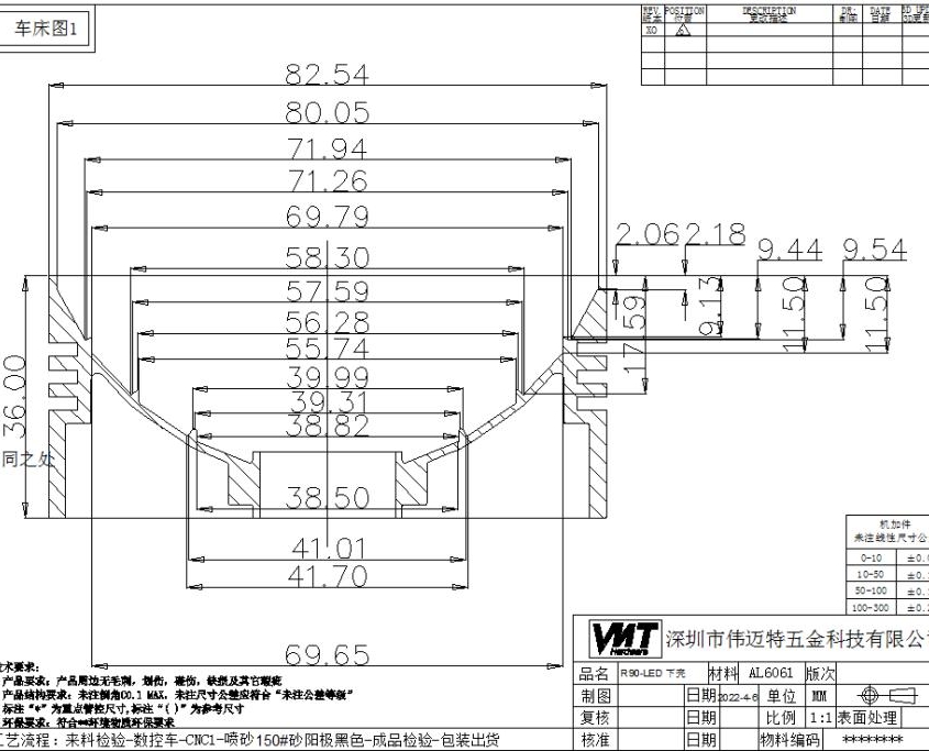
Engineering drawings act as detailed visual instructions, ensuring that the designer’s vision is executed exactly as planned. They are the primary communication tool between designers, manufacturers, and quality control engineers in CNC machining and other manufacturing fields.
Each drawing typically includes dimensions, tolerances, material types, and manufacturing processes, along with engineering drawing symbols that represent various mechanical, electrical, and physical attributes of the components. These drawings often guide CNC machining processes, including CNC milling, CNC turning, and drilling.
Note: If you want to learn more about engineering drawing, you can read the following article: Mechanical Engineering Drawing And Design: A Comprehensive Guide
What Are Engineering Drawings Used For?
Engineering drawings are vital for producing components that meet specific requirements, as they provide detailed visual representation of the design intent.
Designers use engineering drawings to visualize how a product will be constructed and how parts will fit together. Manufacturers use these drawings to create the product with high precision, ensuring all parts are fabricated according to specifications. CNC machining plays a significant role in this process, as it relies on these detailed drawings to create parts with extreme accuracy.
Engineering drawings are essential in industries such as automotive, aerospace, construction, and electronics. In CNC machining, for example, engineering symbols for drawings are used to indicate tool paths, material types, and the necessary finishes for components. In aerospace, for example, these symbols are critical for ensuring that parts meet the strict standards required for aircraft manufacturing.
What Are Engineering Drawing Symbols?
Engineering drawing symbols are graphical representations used in technical drawings to specify key features such as material type, dimension, tolerances, or machining processes. These symbols help standardize information so that everyone involved in the project can understand the design intent. For CNC machining, these symbols are crucial in guiding machine operators and engineers in producing the exact part as designed.
Instead of writing out lengthy descriptions for every part or feature, symbols in drawings provide a quick, standardized way of communicating essential data, saving time and reducing ambiguity. For CNC machining, engineering symbols for drawings guide every step of the process, from the initial design to final machining.
Engineering drawings typically combine several categories of symbols to communicate a complete manufacturing specification:
- Basic dimension symbols
- Geometric dimensioning and tolerancing (GD&T)
- Surface finish symbols
- Technical line conventions
- Hole, thread, and fastener callouts
- Welding, bend, and material symbols
- Drawing standards and projection systems
The sections below cover each of these in detail.
Engineering Drawing Standards
Before interpreting any symbol on a drawing, it’s worth checking which standard the drawing follows. The same symbol can carry slightly different meaning or notation rules depending on the governing standard, which is why the title block typically lists the applicable standard alongside material and revision information.
ASME Y14.5 (North American Standard)
ASME Y14.5 is the dominant GD&T standard used throughout the US and Canada. It defines:
- Geometric tolerances — how much a feature is allowed to deviate in form
- Datum systems and priority — which reference surfaces control a part’s orientation and location
- Feature control frames — how tolerance requirements are structured and read
- Material condition modifiers (MMC, LMC, RFS) — how tolerance can shift based on a feature’s actual size
- Drawing conventions — consistent rules for how information is presented
Aerospace, defense, automotive, and industrial manufacturers based in North America typically default to this standard.
ISO Standards (International Standard)
The ISO framework isn’t a single document — it’s a set of standards, each covering a different part of a drawing:
- ISO 128 — rules for line types and what each one represents
- ISO 1101 — the ISO equivalent to GD&T, covering geometric tolerancing
- ISO 1302 — how surface texture requirements are specified
- ISO 5459 — how datum systems are established and referenced
A symbol that looks identical under ASME and ISO doesn’t always follow the same interpretation rules, so it’s worth confirming which system governs a drawing before assuming based on appearance alone. This framework is widely used across Europe and much of Asia, including China.
First-Angle vs Third-Angle Projection
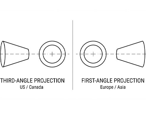
Drawings also specify a projection system, which determines how three-dimensional views are laid out on a two-dimensional sheet. Third-angle projection places the viewer between the part and the projection plane, and is the standard used in the US and Canada. First-angle projection places the part between the viewer and the projection plane, producing a mirrored view arrangement. This is the standard used across Europe and much of Asia, including China.
Mixing up the two systems can lead to features being read in the wrong position or mirrored entirely, so the projection symbol near the title block should always be checked before interpreting views.
What Are the Symbols Used in Engineering Drawings?
Engineering drawing symbols are essential tools for conveying specific characteristics of parts and components. These symbols are designed to represent various features and properties, simplifying the complexity of the design and allowing engineers to communicate intricate details efficiently on a single drawing. In CNC machining, these symbols provide a standardized way to express dimensions, tolerances, surface finishes, and other essential information that directly influences the manufacturing process.
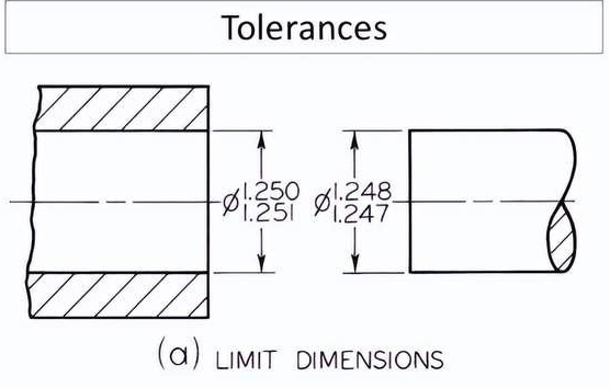
Geometric, Tolerance, and Surface Finish Symbols
These categories of symbols are pivotal in ensuring that the CNC machining process meets the design’s precision requirements.
1. Geometric Symbols: These symbols represent the shape or feature of a part. For example, the circle symbol might represent a hole or bore, while lines can indicate edges, centers, or axes. Geometric symbols like the diameter symbol (⌀) are used to specify the diameter of circular features on a part, while symbols for radius or fillet radius indicate the curvature of a part, which is crucial for operations like CNC milling.
2. Tolerance Symbols: Tolerances specify the allowable limits of variation for a part’s dimensions. These symbols are essential in CNC machining, as they determine how closely a part must be manufactured to its designed dimensions. Geometric Dimensioning and Tolerancing (GD&T) symbols are often used, such as the flatness symbol, perpendicularity, and concentricity, which specify how precise the surfaces and features of the part should be. These symbols ensure that parts will fit together properly when assembled and meet performance requirements.
3. Surface Finish Symbols: These symbols indicate the required finish of the part’s surface after machining. In CNC machining, surface finish is critical to ensure proper function, aesthetics, and part longevity. Surface roughness symbols provide specific details about the type and roughness of the finish, such as Ra or Rt, which are vital for components that require smooth or textured surfaces.
GD&T Symbols
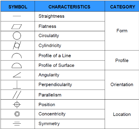
Geometric Dimensioning and Tolerancing (GD&T) controls how much a feature is allowed to vary in form, orientation, or location — and unlike a basic plus/minus tolerance, it can tie that variation to specific reference surfaces on the part, called datums.
Every GD&T requirement is expressed inside a Feature Control Frame, a boxed callout that packs several pieces of information into one symbol: the geometric characteristic being controlled (such as flatness or position), the size of the tolerance zone, and — where relevant — which datums the tolerance is measured from, listed in priority order (primary, secondary, tertiary).
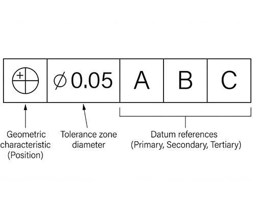
Datum Reference Systems
A datum is a reference surface, edge, or point on a part that other features are measured from. Datums are ranked by priority — primary, secondary, and tertiary — and this order determines how the part is oriented during inspection: the primary datum is checked first, the secondary next, and the tertiary last.
In the Feature Control Frame example above, datums A, B, and C are listed in exactly this priority order — inspection references surface A first, then B, then C, to determine whether the toleranced feature falls within its allowed zone.
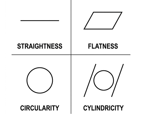
Form Controls
Form controls define how much a single feature is allowed to deviate from its ideal shape. They don’t reference any datum — the feature is checked only against itself.
Straightness
Controls how much a line or axis is allowed to deviate from a perfectly straight path. Common on shafts, guide rails, and linear bearing surfaces.
Flatness
Controls how much a surface is allowed to deviate from a perfectly flat plane. Common on sealing surfaces, mounting plates, and gasket faces.
Circularity (roundness)
Controls how close a circular cross-section is to a perfect circle. Common on shafts, bearing journals, and valve stems.
Cylindricity
Combines roundness and straightness into a single tolerance zone along a cylindrical feature’s full length. Common on hydraulic cylinders and bearing bores.
Profile Controls
Unlike form controls, profile controls can reference datums or stand alone, and are used to control the shape of a line or surface against a defined true profile rather than a simple plane or circle.
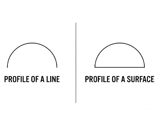
Profile of a Line — Controls how much a two-dimensional cross-section or contour line is allowed to deviate from its theoretically exact profile. Common on cam profiles and cross-sectional contours defined at specific stations along a part.
Profile of a Surface — Controls how much an entire three-dimensional surface is allowed to deviate from its theoretically exact profile. Common on castings, forgings, turbine blades, and other complex curved surfaces.
Orientation Controls
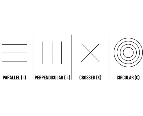
Orientation controls define the allowable angle between a feature and a datum. All three require at least one datum reference, since angle can only be measured relative to something.
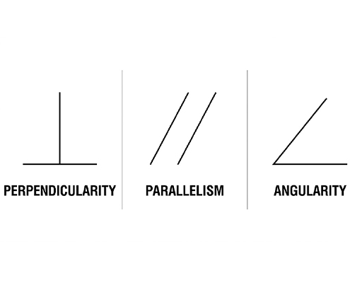
Perpendicularity — Controls how close a feature is to a true 90° angle relative to a datum. Common on mounting faces, locating pins, and dowel holes that must sit square to a reference surface.
Parallelism — Controls how close a feature is to being perfectly parallel to a datum. Common on guide rails, mating surfaces, and slots that must run true to a reference edge or plane.
Angularity — Controls how close a feature is to a specified angle other than 0° or 90° relative to a datum. Common on angled mounting faces, wedge-shaped features, and chamfered surfaces with a critical angle callout.
Location Controls
Location controls define where a feature is positioned relative to one or more datums. All three require datum references, and Position is the most frequently used GD&T symbol overall.
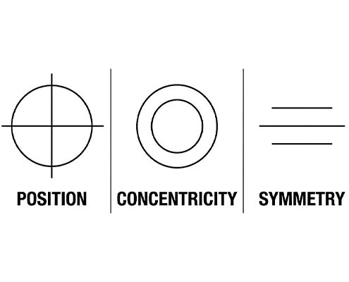
Position — Controls how far a feature’s actual location is allowed to deviate from its true position — the theoretically exact location defined by basic dimensions and datum references. Common on hole patterns, pin locations, and slot centers.
Concentricity — Controls whether the median points of a feature share a common axis with a datum axis. Concentricity is difficult and costly to inspect, and was removed from the ASME Y14.5-2018 standard in favor of position or runout controls, though it may still appear on older drawings.
Symmetry — Controls whether a feature is evenly distributed on either side of a datum plane or axis. Like concentricity, symmetry is difficult to inspect and is no longer recommended under the current ASME Y14.5 standard.
Runout Controls
Runout controls measure how much a surface deviates as the part is rotated 360° around a datum axis. Both require a datum axis, and both are used almost exclusively on rotating components.
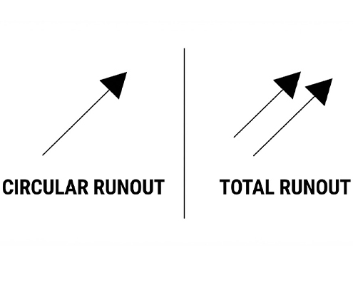
Circular Runout — Checks a single circular cross-section at a time as the part rotates, catching both roundness and centering errors at that specific location. Common on shaft journals and sealing surfaces where each cross-section is checked independently.
Total Runout — Checks the entire surface simultaneously as the part rotates, combining circularity, cylindricity, straightness, and coaxiality into one control. It’s a stricter requirement than circular runout, since the whole surface must stay within the tolerance zone at every point along its length. Common on bearing surfaces and shafts where the full surface must run true.
Surface Finish Symbols
Surface finish symbols specify how smooth or textured a machined surface needs to be, communicating a requirement that plain dimensions can’t capture.
Surface Roughness (Ra)
Ra is the most commonly used surface finish parameter, representing the average roughness of a surface’s peaks and valleys. It’s typically called out in a roughness symbol next to the feature it applies to.
| Surface Finish | Typical Process |
|---|---|
| Ra 12.5 µm | Rough machining |
| Ra 6.3 µm | Standard machining |
| Ra 3.2 µm | Finish machining |
| Ra 1.6 µm | Fine machining |
| Ra 0.8 µm | Grinding |
| Ra 0.4 µm | Lapping / Superfinishing |
Other Surface Parameters
Ra isn’t the only surface finish value used on drawings. A few other parameters show up depending on the industry and application.
Rz — Measures the average peak-to-valley height across the surface. Common in Europe and ISO-based industries as an alternative to Ra.
Rt — Measures the total profile height, from the single highest peak to the single lowest valley. Common on sealing surfaces where an occasional deep scratch matters more than the average roughness.
Waviness — Controls surface variation at a larger scale than roughness, typically caused by machine vibration, deflection, or fixturing. Important in precision sealing and optical applications.
Lay — Specifies the direction of the dominant surface pattern left by machining, such as circular lay from turning or straight lay from milling. Affects sealing performance and friction in mating surfaces.
Material Removal Required / No Material Removal Allowed
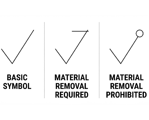
The basic surface finish symbol can be modified with an additional mark to specify whether machining is required or prohibited on that surface.
Material Removal Required — A horizontal bar added across the top of the symbol means the surface must be machined to reach the specified finish, typically through milling, turning, grinding, or honing.
No Material Removal Allowed — A circle added to the symbol means machining is prohibited on that surface. This is common on as-cast, as-forged, or cosmetic molded surfaces that must be used as-produced.
Technical Line Symbols
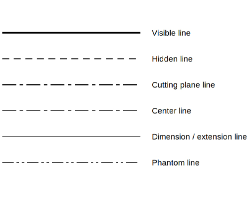
Line types on a drawing aren’t a stylistic choice — each one carries a specific meaning, and misreading one can mean a hidden feature gets overlooked or a part gets machined wrong.
Visible Lines — Thick continuous lines representing edges that can be directly seen in the drawing view.
Hidden Lines — Short dashed lines representing edges or features that are obscured from view, such as internal holes, cavities, or hidden slots.
Cutting Plane Lines — Thick lines with alternating long and short dashes, marking where a sectional view has been taken to reveal internal geometry.
Center Lines — Thin lines with alternating long and short dashes, marking axes of symmetry, hole centers, and rotational axes. These often double as datum references during machining and inspection.
Dimension and Extension Lines — Thin continuous lines used to indicate the size of a feature and the points between which a dimension is measured.
Phantom Lines — Thin lines with a long-short-short-long dash pattern, representing alternate positions of a moving part or the outline of an adjacent part for reference.

Other Common Symbols on Engineering Drawings
Several key symbols are commonly used across various types of engineering drawings, particularly when preparing designs for CNC machining.
| Symbol type | Description | Application in CNC Machining |
| Geometric Symbols | Basic geometric symbols define the size and shape of individual features, such as circular dimensions and drilled or machined depths. | Used to specify hole diameters, arc radii, and pocket or bore depths that CNC programs must machine to. |
| Diameter — Indicated with the Ø symbol before the dimension value. | Confirms the exact bore or shaft diameter a CNC operation must hold, avoiding confusion with a radius callout. | |
| Radius — Indicated with the R symbol before the dimension value. | Guides tool selection and toolpath programming for curved edges, fillets, and rounded corners. | |
| Depth — Written as a dimension followed by “DEEP”. | Sets the Z-axis travel limit for drilling, boring, or pocketing operations. | |
| Spotface — A shallow flat surface for a bolt head or washer to seat against. | Requires a facing or counterboring operation to create a flat, perpendicular seating area before fastening. | |
| Thread Symbols | Represents the type, size, and direction of threads for bolts, screws, and other fasteners | Ensures precise thread cutting and milling for accurate fit and functionality |
| Fillet Radius Symbols | Denotes the curved inside corners of a part to eliminate sharp edges | Enhances part strength, prevents stress concentration, and improves assembly ease |
| Hole Symbols | Specifies hole type, depth, and dimensions for drilled, bored, or through-hole features. | Guides CNC drilling and milling for accurate hole placement, sizing, and depth control. |
| Countersink | Creates a conical recess at a hole’s opening, shown as a callout like “Ø10 C’SINK 90°”, used to seat flat-head screws flush with the surface. | Requires a chamfer or countersinking operation matched to the fastener’s head angle, typically 82° or 90°. |
| Counterbore | Creates a flat-bottomed cylindrical recess, shown as a callout like “Ø12 C’BORE Ø20 × 5 DEEP”, used to seat socket-head cap screws below the surface. | Requires a two-step boring operation: drilling the through-hole, then machining the larger flat-bottomed recess to the specified depth. |
| Welding Symbols | Indicates welding type, size, and process for joining parts | Helps in CNC machining preparation for welding, ensuring structural integrity |
| Bend Radius and Angle Symbols | Defines sheet metal bending curvature and angles | Ensures proper bending operations in CNC laser cutting and punching |
| Material Symbols | Specifies material type such as steel, aluminum, and plastic for manufacturing | Ensures correct material selection for required mechanical, thermal, and chemical properties |
Symbols in Specific Engineering Disciplines
In engineering, symbols are essential for clearly conveying the specifications of components, assemblies, and systems. These symbols are commonly used in mechanical and electrical engineering drawings and help guide CNC machining operations. Below, we explore the specific symbols used in mechanical and electrical engineering and their applications in CNC machining.
Symbols in Mechanical Engineering
In mechanical engineering, specific symbols are used to represent components such as fasteners, shafts, and other mechanical systems. These symbols in mechanical drawing are essential for guiding CNC machining operations, ensuring that each component is fabricated to the correct specifications.
Mechanical Drawing Symbols for Assemblies and Components: Mechanical engineers rely on mechanical drawing symbols to represent common parts like bolts, nuts, screws, and washers. Each of these symbols conveys detailed information about the size, material, and tolerance of the part, which is crucial when manufacturing these components with CNC machines.
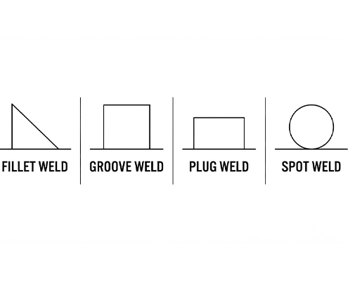
Common Symbols in Mechanical Drafting: Some frequently encountered symbols in mechanical drafting include the bolt symbol, which represents the shape and size of bolts, and the weld symbol, which indicates the type of weld to be used, its size, and the weld’s location—critical information for CNC turning and CNC milling processes.
Thread and weld callouts carry more detail than most other symbols on a drawing. A thread designation such as M10 × 1.5 or 1/4-20 UNC specifies both the thread diameter and pitch, and getting either wrong means the fastener won’t engage correctly. Weld symbols follow a similar logic — a fillet weld, groove weld, plug weld, and spot weld each call for a different joint preparation and welding process, so misreading which one is specified can compromise the joint’s structural integrity.
Symbols in Electrical Engineering
In electrical engineering, specialized symbols are used to design electrical circuits, control systems, and wiring diagrams. These symbols engineering play an important role in producing electrical components that must meet precise specifications, often required in CNC machining of electrical parts like connectors and casings.
Electrical Symbols for Circuits, Wiring, and Components: Symbols such as the resistor, capacitor, and diode are used to represent electrical components. These electrical engineering symbols help engineers visualize how components are connected in a circuit, ensuring that CNC machining operations for producing electrical components, like connectors and terminals, are executed accurately.
Electrical Engineering Drafting Standards: The symbols in electrical engineering must follow international standards like IEC 60617 or ANSI Y32.2 to ensure that all electrical components and wiring diagrams are universally understood. These standards also guide CNC machining of electrical parts, ensuring that they fit into larger systems precisely.
Symbols in Process & Instrumentation (P&ID)
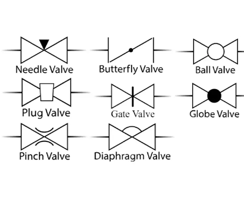
Process and Instrumentation Diagrams (P&IDs) use a separate symbol set to represent how valves, pumps, compressors, and instrumentation connect within a process system. These drawings are common in chemical processing, oil and gas, and energy industries, where components like valve bodies, flanges, and instrument housings are frequently produced through CNC machining to meet precise fit and pressure requirements.
How to Read Engineering Drawings Symbols?
Reading engineering drawing symbols accurately is essential for interpreting a drawing correctly, particularly when translating these symbols into CNC machining instructions. For companies like VMT, which specialize in high-precision CNC machining services, understanding the meaning behind each symbol is crucial for achieving the desired product quality.
1. Learn Basic Shapes and Lines
Start with the basic shapes and lines used in engineering drawings. Once familiar, move on to more complex symbols like surface finishes, material types, and tolerances. Understanding these symbols is essential for creating CNC toolpaths and preparing for operations like CNC turning and milling. At VMT, we ensure that each drawing is carefully reviewed for accurate CNC processing.
2. Understand Symbol Placement and Context
The placement of symbols in a drawing is crucial. They indicate features like holes, slots, or fasteners and their positioning. At VMT, we emphasize understanding how symbols relate to the overall drawing to guide CNC machining accurately. This helps operators determine the correct sequence and settings for machining, ensuring the final product meets all specifications.

3. A Step-by-Step Reading Sequence
Jumping straight to dimensions is a common mistake — a few minutes spent on the basics below can prevent a costly misread.
- Check the Title Block — Confirm the drawing number, revision level, material, governing standard, and units before reading anything else. Machining an outdated revision is one of the most common and preventable errors on a shop floor.
- Confirm the Projection System — Identify whether the drawing uses first-angle or third-angle projection before interpreting any views, to avoid reading feature positions in reverse.
- Identify Datums Before Reading GD&T Callouts — Locate the primary, secondary, and tertiary datums first, since every Feature Control Frame is measured relative to them.
- Review Critical Characteristics — Scan the drawing for GD&T callouts, surface finish requirements, thread specifications, and critical dimensions before starting to plan machining operations.
- Evaluate Inspection Requirements — Confirm that the specified tolerances can actually be measured with available equipment. Catching this before machining begins, rather than after, avoids disputes over parts that were made correctly but can’t be verified.
- Cross-check Unfamiliar Symbols Against the Abbreviations List — Confirm any uncertain callout against the abbreviations table before assuming its meaning.
Why Use Abbreviations and Symbols in Engineering Drawings?
Abbreviations and symbols are critical for streamlining communication and reducing the size of drawings. CNC machining benefits greatly from these symbols, as they reduce the complexity of designs while ensuring that all necessary information is conveyed.
By using symbols like symbols in drafting for common features, engineers can avoid repetitive descriptions and focus on the essential information, saving space and time. For CNC machining, these symbols ensure that the machine operators and engineers understand the exact machining requirements.
Abbreviations and engineering symbols help to standardize communication between teams, ensuring that everyone understands the drawing without ambiguity. For instance, the TOL abbreviation denotes “tolerance,” which is crucial in defining the acceptable variation in part dimensions that is important for CNC machining accuracy.
Common Engineering Drawing Abbreviations
Abbreviations play a critical role in reducing clutter and streamlining the information presented in engineering drawings. By using abbreviations, engineers can convey a large amount of information in a compact and easily readable format. In CNC machining, these abbreviations are especially valuable for ensuring that all specifications are communicated clearly and without ambiguity. Proper use of abbreviations allows for a more efficient and effective manufacturing process, as it eliminates confusion and enhances precision.
Frequently Used Abbreviations in Engineering Drawings
Several abbreviations are commonly used in engineering drawings to represent essential details. Some of the most frequently used abbreviations include:
| Abbreviation | Description | Application in CNC Machining |
|---|---|---|
| DIM | Dimensions | Specifies the measurements of features such as length, width, height, diameter, and depth |
| TOL | Tolerance | Defines the allowable variation in a part’s dimensions for proper fit and function |
| ISO | International Organization for Standardization | Sets guidelines for technical specifications, including quality, dimensions, and tolerances |
| R | Radius | Indicates the size of a curved edge or feature, such as the radius of a corner or hole |
| Ø | Diameter | Denotes circular features such as holes or shafts |
| BOM | Bill of Materials | Lists all components, parts, and materials required for a project |
| C.S.K. | Countersunk | Specifies a hole with a conical opening at the top, often for seating a screw or bolt |
| C.Bore | Counterbore | Refers to a cylindrical hole with a flat bottom |
| T.B.D. | To Be Determined | Used when certain details like dimensions or materials are not finalized |
| L.D. | Lead | Refers to the lead of a thread in a threaded part |
| THRU | Through | Indicates a hole or feature extends completely through the part thickness |
| TYP | Typical | Indicates a feature repeats at multiple locations on the drawing, so it’s only dimensioned once |
| REF | Reference | Marks a dimension provided for information only, not used for inspection or acceptance |
| MAX / MIN | Maximum / Minimum | Specifies the upper or lower limit allowed for a dimension |
| CL | Centerline | Marks the axis of symmetry or center reference for a feature |
| PCD | Pitch Circle Diameter | Specifies the diameter of the circle on which a bolt hole pattern is centered |
| NTS | Not To Scale | Warns that the drawing isn’t proportionally accurate and dimensions shouldn’t be estimated visually |
Inspection Methods for Common Symbols
Different symbols call for different inspection tools. A caliper can’t verify a position tolerance, and a profilometer won’t tell you if a hole is round.
| Symbol / Characteristic | Common Inspection Method |
|---|---|
| Basic dimensions (diameter, radius, depth) | Calipers, micrometers |
| Flatness, Straightness | Surface plate + dial indicator |
| Position, Concentricity | CMM (Coordinate Measuring Machine) |
| Circularity, Cylindricity | Roundness tester, CMM |
| Profile | CMM |
| Surface roughness (Ra) | Profilometer |
| Thread specifications | Thread gauges |
| Runout | Dial indicator + V-block or rotary table |
Specifying a tolerance without considering how it will be measured is a common source of friction between designers and suppliers — a requirement that looks reasonable on paper can demand equipment or inspection time that adds significant cost to the part.
From Drawing to Manufacturable Part
Have a part drawing but not sure if every detail is ready for manufacturing?
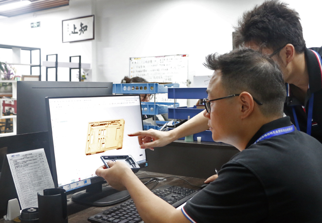
Send us your 2D drawing or 3D CAD file. Our engineers will review critical dimensions, tolerances, materials, and manufacturing requirements to identify potential issues before production
Get a Free Drawing Review →Start Your CNC Machining Project with VMT
At VMT, we specialize in producing high-precision CNC-machined parts for a wide range of industries, including automotive, medical, industrial equipment, and electronics. With over 14 years of experience in CNC machining, we have honed our skills and techniques to consistently deliver top-tier results. Whether you’re looking to produce complex, intricate parts or high-volume production runs, VMT is your trusted partner in precision manufacturing.
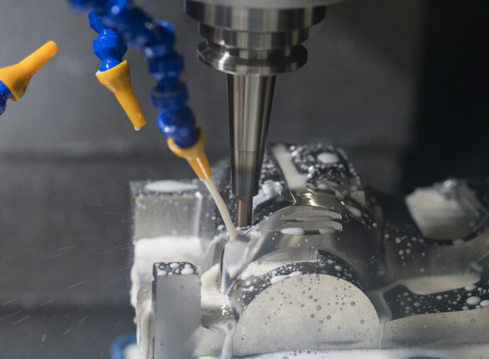
By utilizing the correct engineering drawing symbols and adhering to rigorous standards, we ensure that every part is fabricated to exact specifications. This attention to detail enables us to provide exceptional quality and consistency in CNC manufacturing. Our team of engineers, each with over 20 years of experience, works closely with clients to interpret engineering drawings, ensuring the highest accuracy and the best possible outcomes for each project.
Frequently Asked Questions About Engineering Drawing Symbols
How to Read Mechanical Engineering Drawing Symbols?
Mechanical engineering drawing symbols represent components, materials, and processes. To read them, start by understanding the key (legend) that defines each symbol. Familiarize yourself with standard symbols like lines (solid, dashed), shapes (circles, squares), and notations (diameters, angles). Additionally, pay attention to scale, dimensions, and tolerances to accurately interpret the drawing’s details.
What are the 4 Basic Components to Dimensioning?
The four basic components of dimensioning are:
Size dimension – indicates the size of an object.
Location dimension – specifies the position of features.
Angular dimension – shows the angle between features.
Tolerance – defines the allowable variation from the specified dimension, ensuring fit and function.
What are PFD Symbols?
PFD symbols (Process Flow Diagram) represent the major equipment and processes in a system. These symbols simplify complex processes, showing key elements like pumps, compressors, heat exchangers, and pipelines. They focus on the flow of materials and energy, often omitting intricate details for a broader understanding of the process layout.
How do Engineering Drawings, PFDs, and P&IDs Relate?
Engineering Drawings, PFDs, and P&IDs are all essential tools in process design and engineering. Engineering drawings detail individual parts and components, while PFDs show the overall flow of materials and energy in a system. P&IDs (Piping and Instrumentation Diagrams) provide a more detailed, specific look at the piping, instrumentation, and control systems in the process. All three tools work together to communicate design intent and system operation.
What’s the difference between a counterbore and a countersink symbol?
A counterbore creates a flat-bottomed cylindrical recess for a socket-head cap screw to sit below the surface. A countersink creates a conical recess for a flat-head screw to sit flush with the surface. The two are easy to confuse on a drawing since both are used to recess a fastener head, but the shape of the recess and the screw type they’re designed for are different.
What’s the difference between circularity and cylindricity?
Circularity controls how round a single cross-section is, checked independently at each point along a part. Cylindricity controls the entire cylindrical surface at once, combining roundness and straightness into a single 3D tolerance zone. A part can pass a circularity check at every cross-section and still fail cylindricity if the diameter tapers or bows along its length.
Why is concentricity rarely used on modern drawings?
Concentricity is difficult and expensive to inspect, since it requires locating the median points of a feature rather than measuring a surface directly. ASME Y14.5-2018 removed it from the standard in favor of position or runout controls, which achieve a similar result with more practical inspection methods. It may still appear on older drawings, but new designs typically avoid it.
What’s the difference between profile of a line and profile of a surface?
Profile of a line controls a two-dimensional cross-section or contour, checked at specific stations along a part. Profile of a surface controls an entire three-dimensional surface at once. The symbols look similar, but profile of a surface is a closed shape while profile of a line is open, reflecting the difference between controlling a single contour and controlling a whole surface.
SHENZHEN VMT METAL PRODUCT CO., LIMITED
 WhatsApp/WeChat/Mobile:
+86-15099911516
WhatsApp/WeChat/Mobile:
+86-15099911516 Tel: 86-150-9991-1516
 QQ: 939020977
 E-Mail: service@vimetal.com.cn
Latest Blogs
 Materials Used in CNC Prototyping: A Comprehensive GuideSeptember 9, 2026 - 10:55 am
- CNC Prototyping Cost Guide: How to Estimate, Breakdown, and Reduce Your BudgetSeptember 7, 2026 - 11:30 am
- Comprehensive Guide to Rapid Prototyping Methods: Types, Comparison and SelectionSeptember 3, 2026 - 8:32 am
- Chromate Conversion Coating: Is This Suitable for Your Aluminum CNC Machined Parts?August 29, 2026 - 9:02 am
- What is Aircraft Grade Aluminum? Complete Guide to Aerospace AlloysAugust 21, 2026 - 8:32 am