Surface Finish Symbols In Engineering Drawings: A Comprehensive Guide
Poor understanding of surface finish symbols can lead to costly machining errors, poor component performance, and even project failures. Engineers and machinists who misinterpret finish requirements may face rejected parts, rework, and client dissatisfaction. Learning to read and apply surface finish symbols correctly is crucial to delivering precision parts.
Surface finish symbols represent standardized instructions on technical drawings, guiding machinists on how smooth or rough a finished surface must be. Correctly reading these symbols ensures parts meet functional, aesthetic, and quality standards while reducing manufacturing errors.
Let’s dive deeper into surface finish symbols, uncovering their meaning, usage, and importance in modern CNC machining.
Why Are Surface Finish Requirements Important in Engineering?
Surface finish requirements define the allowable surface texture created during manufacturing, ensuring each part fits, moves, and operates correctly within its design environment. Meeting specified finishes protects performance integrity and minimizes the chance of failure under stress or environmental exposure.
Understanding surface finish is vital for achieving design success, especially in industries demanding high-precision CNC machining such as aerospace, automotive, and medical device manufacturing.

What Is Surface Roughness and How Is It Measured?
Surface roughness measures the fine irregularities on a material’s surface. High roughness may create friction and weaken structural integrity, while ultra-smooth surfaces may require special processes to achieve. Misunderstanding roughness specifications can cause functional issues, increased costs, or even product recalls.
Surface roughness is quantified by metrics such as Ra and Rz, typically indicated via surface roughness symbol or surface texture callout on engineering drawings. Specialized instruments, such as contact profilometers or optical surface scanners, are used to accurately measure surface characteristics.
Common Surface Roughness Parameters
Surface roughness parameters are essential for defining and assessing the quality of machined surfaces in CNC manufacturing. Each parameter measures different aspects of the surface texture, such as average roughness, peak-to-valley height, and maximum height. These parameters help ensure the machined parts meet their intended functional and aesthetic requirements.
| Parameter | Unit | Typical Range | Application |
|---|---|---|---|
| Ra | µin/µm | 8–500 µin (0.2–12.5 µm) | General machining, moderate precision |
| Rz | µm | 2–100 µm | Fine finishing, precision surfaces |
| Ry | µm | 10–300 µm | Critical parts, sealing surfaces |
| Rt | µm | 5–300 µm | Functional surfaces with high roughness |
| Rmax | µm | 10–500 µm | Peak-to-valley measurement for key tolerances |
How to Read Surface Finish Symbols on Drawings?
Surface finish symbols are the standardized language that communicates surface texture requirements in engineering drawings. Misreading these symbols can result in non-conformance, leading to costly rework or rejected parts.
1. Ra Value
The Ra value defines the allowable surface roughness, expressed as the arithmetic average of the surface deviations. For example, an Ra = 1.6 µm specifies a moderately smooth surface suitable for general-purpose components. This value ensures that the surface meets both functional and aesthetic standards required by the design.
2. Lay Pattern
The lay pattern indicates the direction of the machining marks left on the surface during manufacturing. Common lay patterns include:
Parallel (||): Marks run parallel to the axis, often seen in turning or grinding.
Crossed (X): Marks intersect at an angle, usually from multi-directional machining.
Circular (O): Marks follow a circular pattern, typical of lathe work.
Understanding the lay pattern helps align machining with functional requirements, such as load-bearing or sealing surfaces.
3. Manufacturing Process Notes
Surface finish symbols may include notes specifying additional processes such as grinding, polishing, or honing. For instance, a note stating “grind to Ra ≤ 0.8 µm” directs the machinist to achieve a specific roughness through grinding.
How to Interpret Numbers and Symbols on Engineering Drawings?
Surface finish symbols and numbers on engineering drawings are precise guidelines for achieving the desired surface texture of a machined part. Understanding these details is critical for ensuring functionality, aesthetics, and cost-effectiveness.
1. Numbers Indicating Roughness Values
The numbers next to a surface finish symbol specify the allowable surface roughness, typically measured in Ra or parameters like Rz or Rt. For example, “Ra 16” denotes a smooth surface often achieved through fine grinding or polishing. These values ensure the part meets its functional requirements, such as minimizing friction or creating a proper seal.
2. Symbols for Machining Patterns and Directions
Surface finish symbols may include additional markings to indicate the required machining pattern. Parallel lines suggest machining marks should align with an axis, while crosshatch patterns imply intersecting marks for enhanced grip or oil retention. Circular marks are used for symmetrical surfaces, such as those created by turning operations. These patterns ensure the surface texture supports its intended application.
3. Notes on Surface Finish Tolerances
Many drawings provide additional notes to clarify the finishing process or permissible deviations. For instance, a note like “Grind to Ra ≤ 0.8 µm” explicitly requires grinding to meet the specified smoothness, while “No visible machining marks” demands a mirror-like finish achieved through polishing.
Surface Finish Symbols vs. Surface Treatment Specifications
Distinguishing between surface finish symbols and surface treatment specifications is crucial for manufacturing high-quality parts. Misinterpretation can lead to non-conforming products or functional failures.
1. Surface Finish Symbols: Defining Machined Texture
Surface finish symbols specify the texture directly resulting from machining processes. For example, a callout of Ra 32 µin indicates the surface roughness that must be achieved during machining, which influences the part’s functionality and appearance. This requirement is met using proper tooling, feed rates, and other machining parameters.
2. Surface Treatment Specifications: Post-Processing Operations
Surface treatment specifications refer to processes applied after machining, such as anodizing, coating, or heat treatment. These treatments modify the surface properties to improve corrosion resistance, wear resistance, or aesthetics. Unlike surface finish symbols, these specifications focus on enhancing the material rather than its initial texture.

3. Importance of Differentiation
Machining surface finishes and post-processing treatments serve distinct purposes. Confusing them can lead to skipped processes, over-polished surfaces that disrupt coating adhesion, or failure to meet functional requirements. Understanding their differences ensures a balanced approach to production.
4. Best Practices for CNC Shops
To avoid errors, CNC shops must carefully review drawings, document machining and treatment steps separately, and ensure surface roughness is measured before post-processing. Clear communication with clients helps resolve ambiguities in drawings and prevents missteps.
Common Mistakes When Specifying Surface Finish Requirements
Clear communication of surface finish requirements is essential for avoiding production issues. Below are common mistakes, their causes, and the impacts they have on production:
| Mistake | Cause | Impact | Solution |
|---|---|---|---|
| Over-Specifying Finishes | Specifying tighter finishes than functionally necessary. | Increases machining time, tool wear, and costs without adding value to the part. | Align finish requirements with functional needs through consultation between design and production teams. |
| Under-Specifying Finishes | Failing to specify appropriate finishes for critical parts. | Leads to performance issues such as poor sealing, increased friction, or premature wear. | Identify critical surfaces and match roughness to functional requirements during the design phase. |
| Ambiguous Callouts | Using vague or unclear symbols or not providing sufficient detail. | Causes misinterpretation by machinists, resulting in non-conforming parts or rework. | Use standardized surface finish symbols and include detailed notes where necessary. |
| Ignoring Process Capabilities | Specifying finishes beyond the capabilities of available machines or tools. | Causes production delays as additional processes or equipment may be needed. | Match surface finish requirements to the shop’s machining capabilities during the planning stage. |
| Neglecting Post-Processing Effects | Overlooking the impact of treatments like coatings or anodizing on surface texture. | Post-processes may alter the surface finish, leading to non-compliance with specifications. | Account for changes to surface roughness caused by treatments and communicate expectations clearly. |
| Inadequate Inspection Procedures | Failing to define or perform proper roughness measurements. | Parts may pass undetected with incorrect finishes, leading to functional failures in the field. | Establish clear inspection protocols and use calibrated tools to m |
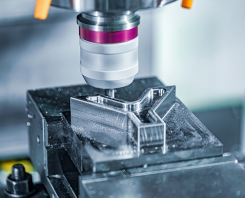
How Surface Finish Affects CNC Machining Processes?
Surface finish requirements directly influence the selection of machining processes, tools, and parameters. Below is a breakdown of how various machining methods achieve specific roughness levels:
1. CNC Milling: Achieving Moderate Roughness
Milling typically produces surface roughness values ranging from 32–125 µin Ra. This process is suitable for general-purpose parts where moderate precision is acceptable. However, milling alone may not meet the requirements for components needing smoother finishes, necessitating additional finishing steps like grinding or polishing.
2. Grinding: Precision Finishing
Grinding is used for achieving finer surface finishes in the range of 8–32 µin Ra. It is ideal for parts with tight tolerances and surfaces that interact with seals or bearings. Misinterpreting a grinding requirement on a drawing can lead to skipping this crucial step, potentially compromising the part’s functionality.
3. Lapping and Polishing: Ultra-Smooth Finishes
Lapping and polishing techniques are employed to achieve surfaces smoother than 8 µin Ra, suitable for critical applications such as optical components or high-precision sealing surfaces. These methods are resource-intensive and should only be specified when absolutely necessary to avoid excessive costs.
4. Importance of Choosing the Right Method
Selecting the wrong machining process due to a misinterpretation of surface finish symbols can lead to production inefficiencies, increased rework costs, and client dissatisfaction. For instance, using milling instead of grinding for a critical sealing surface may result in a part that doesn’t meet performance expectations.
Start Your CNC Machining and Surface Finishes Project at VMT
VMT specializes in precision CNC machining services where understanding surface finish symbols is second nature. With over 100 CNC machines and surface finishes sieves, VMT delivers superior finishes at competitive lead times.

In Conclusion
Mastering surface roughness symbols, machining techniques, and accurate measurement is crucial for successful CNC manufacturing. Attention to detail ensures parts meet quality and functional standards, avoiding costly errors and maintaining client satisfaction.
Frequently Asked Questions About Surface Finish Symbols In Engineering Drawings
What is The Symbol for Surface Finish?
The symbol for surface finish is a checkmark-like symbol (⌯) often placed on technical drawings. It indicates that a specific surface texture or roughness requirement applies. Variations of the symbol can show whether material removal is needed, and additional numbers or notes specify the roughness level.
What is 0.8 μm Surface Finish?
A 0.8 μm surface finish refers to the roughness average (Ra) of the surface texture, measured in micrometers (μm). It means the surface has very fine irregularities, suitable for applications requiring smooth finishes, like sealing surfaces or precision parts. Lower Ra values like 0.8 μm indicate smoother surfaces.
What is Ra and Rz?
Ra measures the average height of surface irregularities from the mean line over a given length. Rz measures the average height difference between the highest peak and the lowest valley within five sampling lengths. Rz is usually higher and shows more extreme variations.
How Do You Identify Surface Finish?
Surface finish is identified by measuring the surface’s roughness using tools like a profilometer, comparing it against standards, or checking the finish symbol and value on technical drawings. Visual comparison using roughness sample blocks is also common in production to quickly check surface texture quality.