Mastering GD&T Symbols: Tips for Engineers and Technicians
Manufacturers lose money every year due to misinterpretation of drawings. 63% of quality failures are due to the misapplication of GD&T symbols. This guide explains each symbol using industry-proven interpretation techniques.
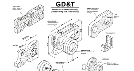
Geometric Dimensioning and Tolerancing (GD&T) standardizes the communication of design intent in accordance with ASME Y14.5. Key symbols such as Ⓜ (MMC), ⌭ (Cylindricity), and ⌓ (Profile) control functional relationships beyond linear dimensions. Mastering these symbols can avoid 80% of machining rework through clear tolerance zone definition.
What Is GD&T?
Geometric Dimensioning and Tolerancing (GD&T) is an engineering communication system that revolutionizes how we define and control part geometry. Developed by the American Society of Mechanical Engineers (ASME) in their Y14.5 standard, GD&T provides a comprehensive symbolic language that addresses the limitations of traditional plus/minus tolerancing.
How Does GD&T Work?
GD&T establishes precise geometric controls through standardized feature control frames that specify three key elements: the geometric characteristic symbol (like ⌖ for position), tolerance value, and relevant datums. Unlike traditional plus/minus tolerancing that only defines dimensional limits, GD&T creates 3D tolerance zones around theoretically perfect geometric forms, controlling how features may vary in form, orientation, and location relative to functional datums.
Core Components of GD&T
Geometric Dimensioning and Tolerancing (GD&T) provides a symbolic language used on engineering drawings and CAD models to define allowable variation in form, orientation, and location of features.
1. Form Controls
Form controls ensure that the basic geometry of a surface or feature is maintained without being affected by its orientation or position in space.
-
Flatness (⌓):
Controls how much a surface can deviate from a theoretically perfect flat plane. Flatness applies to individual surfaces and is critical in sealing applications or mating surfaces.
-
Straightness (—):
Regulates the straightness of a feature, which could be a surface or a feature’s axis. It’s often used on shafts or edges to prevent bowing or warping.
-
Circularity (○):
Also known as roundness, this control ensures that all points on a circular surface lie equidistant from a common center. It applies to individual cross-sections of cylinders or cones.
-
Cylindricity (⌭):
A compound control that ensures the entire cylindrical surface is both circular and straight along its axis. It is used when high precision is needed for rotating parts like pistons or bearings.
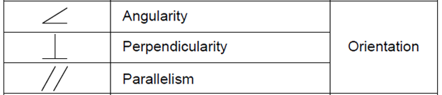
2. Orientation Controls
Orientation controls define the tilt or inclination of a feature relative to a datum, ensuring angular relationships are maintained.
-
Perpendicularity (⊥):
Ensures that a surface, axis, or center plane is exactly 90° to a specified datum. It is essential in applications where square alignment is critical, such as gears and brackets.
-
Angularity (∠):
Controls the angle between a feature and a datum other than 90°. This is useful for parts requiring a precise slope or taper, such as cam surfaces.
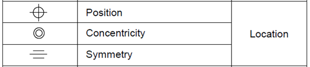
3. Location Controls
Location controls govern the placement of features such as holes, slots, or pins to ensure proper function and assembly.
-
Position (⌖):
The most flexible and commonly used location control. It defines the exact location of a feature in relation to datums, while allowing for toleranced variation. This is key for hole patterns, bolts, and assembly alignment.
-
Concentricity (◎):
Ensures that the median axes of cylindrical features share the same axis. It’s vital for rotating parts like shafts and sleeves, but difficult to measure precisely.
-
Symmetry (⌯):
Controls how symmetrical a feature is about a central datum plane. It ensures balance and even distribution of features, often used in aesthetic or functional designs like casings or housings.
4. Runout Controls
Runout controls manage how surfaces behave when the part is rotated about an axis, combining form, orientation, and location into a single control.
-
Circular Runout (↗):
Controls variations in circular elements during rotation at a single cross-section. It detects imperfections like wobble or lobing on rotating surfaces.
-
Total Runout (↘):
Applies across the entire length of a surface, controlling the combined effects of straightness, roundness, and profile during full rotation. It’s essential in precision rotary components like spindles or shafts.
Essential GD&T Symbols Every Machinist Should Know
Geometric Dimensioning and Tolerancing (GD&T) is the language of precision in manufacturing. Understanding the most commonly used symbols is essential for machinists to interpret designs correctly and ensure parts meet functional and quality standards. Below is a quick reference table of essential GD&T symbols, their key applications, and practical tips from real-world machining scenarios.
| Symbol | Name | Key Application | Practical Tip |
|---|---|---|---|
| ⌓ | Profile | Optical surfaces, complex contours | Critical for achieving Ra 0.2µm finishes on our fine grinding machines |
| Ⓜ | MMC | Bearing seats, press fits | Allows up to 30% more tolerance while maintaining function |
| ⌭ | Cylindricity | Hydraulic rods, precision shafts | Ensures 0.005mm roundness on our grinding lathes |
| ↔ | Position | Hole patterns, mounting features | Maintains 0.01mm accuracy across multiple features |
| ∠ | Angularity | Tapered fits, wedges | Controls angle within 0.02° on complex parts |
Geometric Dimensioning and Tolerancing (GD&T) vs. Traditional Tolerancing
The choice between traditional coordinate tolerancing and geometric dimensioning and tolerancing (GD&T) in precision grinding operations can significantly impact part quality, production efficiency, and overall product performance. Here are the key differences and benefits of implementing GD&T in high-precision grinding applications:
| Control Aspect | Traditional Method | GD&T Method | Technical Advantages | Operational Benefits |
|---|---|---|---|---|
| Cylindrical Features | ±0.05mm diameter tolerance | ⌭0.02mm cylindricity | • 60% tighter geometric control | • 30% easier machining process • 40% less inspection time • Better part functionality |
| Surface Flatness | 0.1mm over 100mm | ⌓0.03mm profile | • Controls entire surface rather than individual points | • 70% reduction in assembly force • Improved load distribution • Better wear resistance |
| Hole Position | ±0.2mm coordinate tolerance | ⌀0.1mm position @ MMC | • Incorporates bonus tolerance concept • Clear functional datum references |
• 40% more usable clearance • Easier fastener installation • Better fatigue performance |
| Angular Features | ±1° angular tolerance | ∠0.5° angularity | • Precise angular control relative to datums | • 50% more precise angular relationships • Reduced stress concentrations |
| Complex Contours | Multiple ± tolerances | Single ⌓ profile tolerance | • Unified control of entire feature |
VMT Meets Your Machining Needs with Precision GD&T Compliance
At VMT, we don’t just manufacture custom parts — we engineer precision. Our CNC machining processes are fully compliant with GD&T standards to ensure every feature meets your design intent. From form and orientation controls to precise feature locations and runout tolerances, we guarantee the accuracy of critical geometries such as flatness, parallelism, true position, and total runout.
In Conclusion
GD&T transforms good parts into great ones by aligning design intent with manufacturing capability. At VMT, we’ve mastered applying GD&T across our classification of grinding machine portfolio to deliver unmatched precision and reliability. Our expertise ensures your parts meet the most demanding specifications while optimizing production efficiency.
Frequently Asked Questions About GD&T Symbols
How many GD&T Symbols?
There are 14 standard GD&T symbols defined by ASME Y14.5. These symbols represent geometric controls categorized into Form, Orientation, Location, and Runout. Each symbol conveys a specific tolerance requirement such as flatness (⌓), position (⌖), or total runout (↘). They are used to ensure consistent quality and function across manufactured parts.
How to Read GD&T Symbols?
To read GD&T symbols, start with the feature control frame, which includes: the symbol (e.g., ⌖ for position), the tolerance value, any modifiers (like MMC or LMC), and the datum references (e.g., A|B|C). Understanding these parts tells you how a feature must be controlled relative to datums and allowed variation.
What are GD&T Symbols?
GD&T symbols are standardized icons that represent specific geometric tolerances on engineering drawings. They define how a feature should be shaped, oriented, located, or controlled during rotation. These symbols help communicate exact design intent, improving manufacturing precision and inspection consistency. Examples include ⊥ (perpendicularity), ‖ (parallelism), and ○ (circularity).
How Many GD and T Symbols?
There are 14 core GD&T symbols used internationally. These symbols cover geometric characteristics such as form (4 types), orientation (3), location (3), and runout (2). By applying them, designers can specify functional limits on shape and alignment, beyond just size dimensions. They ensure interoperability between design, production, and inspection.
What does the Square Circle Symbol Mean in GD&T?
The “square circle” symbol ⌖ in GD&T stands for “True Position”. It defines the exact theoretical location of a feature, such as a hole or slot, relative to datums. Position is the most versatile and commonly used GD&T control, allowing for complex tolerancing of patterns and features across 2D or 3D space.