Taper Turning: Definition, Work, Methods and Advantages

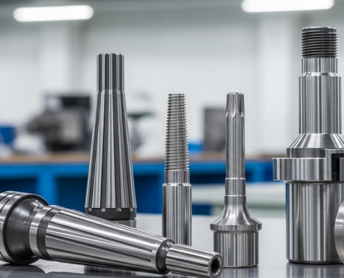
Taper turning is a machining process used to create a conical surface on a workpiece, where the diameter changes uniformly along its length. It is fundamental in manufacturing for components requiring precise fits, such as shafts, valve seats, and tooling. Key methods include the form tool, compound rest, tailstock set-over, and taper attachment methods, each suited for different angles and lengths.
Imagine facing inconsistent taper accuracy, crippling production with high scrap rates, and scrambling to meet tight deadlines for critical components. Many manufacturing engineers and machinists grapple with the frustration of unreliable taper turning processes, struggling to select the optimal method or accurately calculate the precise machine settings needed.
This guide provides authoritative solutions, leveraging expert methodologies to help you understand, execute, and master taper turning, bringing unparalleled precision and efficiency to your manufacturing.
Taper turning is a specialized machining operation essential for creating conical shapes on cylindrical workpieces. This process is fundamental across numerous industries, enabling the production of components that require precise interference fits or specific functional geometries. Mastering the principles of taper turning is key to achieving high-quality, reliable parts.
Taper turning refers to the process of producing a conical surface on a workpiece, where the diameter gradually increases or decreases from one end to the other. Unlike straight turning, which creates a uniform cylindrical shape, taper turning intentionally introduces an angle, resulting in a progressive change in diameter.
This precise shaping is achieved on a lathe by setting the cutting tool to traverse the workpiece at a specific angle relative to its axis of rotation. The resulting surface is either an external cone (male taper) or an internal cone (female taper), depending on the operation.
Tapered components are indispensable in a vast array of engineering applications due to their unique functional advantages. They provide exceptional concentricity, allowing for very precise self-centering fits when two tapered parts are assembled. This characteristic is crucial for applications requiring high rotational accuracy or robust alignment, such as machine tool spindles and precision jigs.
Furthermore, the wedge action of a taper creates a strong, self-locking connection, preventing loosening under vibration or dynamic loads. This makes them ideal for securing cutting tools, mounting pulleys, or ensuring leak-proof seals in fluid systems. Their ability to transmit torque efficiently and offer easy disassembly without damaging components.
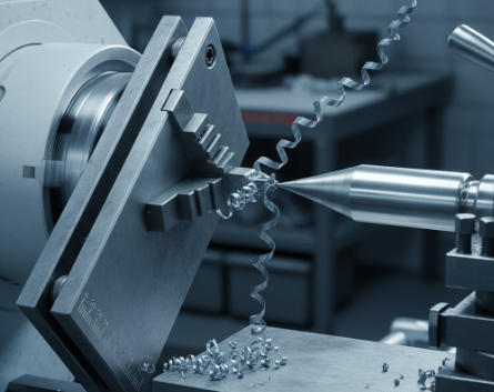
Taper turning fundamentally involves setting the cutting tool or the workpiece itself to move at an angle relative to the lathe’s axis of rotation. The workpiece is securely held in the lathe chuck and supported by the tailstock, similar to cylindrical turning. However, instead of the cutting tool moving parallel to the axis, one of several mechanisms is engaged to create the desired taper. This can involve manually offsetting the tailstock, angling the compound rest, using a dedicated taper turning attachment, or programming a multi-axis CNC machine.
As the tool progresses along the length of the workpiece, it removes material, gradually decreasing or increasing the diameter according to the set angle. The accuracy of the resulting taper depends critically on the precision of the initial setup, the stability of the machine, and the correct calculation of the required angle or offset.
Choosing the right taper turning method affects machining accuracy, production efficiency, and how well the process fits different component shapes. Understanding each method helps in selecting the most effective approach for a given job.
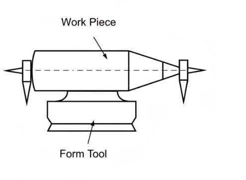
In the form tool method a cutting tool is shaped to match the required taper angle. The tool moves directly into the rotating workpiece to cut the taper. This process is quick and simple, making it suitable for short and steep tapers or mass production of identical parts. It is not suitable for long or shallow tapers because the large cutting area creates heavy forces that may cause vibration, poor surface quality, and tool wear. The cost of making custom form tools is also high, especially for small production batches.
The combining feeds method is common in CNC turning. The machine controls both the longitudinal and cross feeds at the same time to produce the desired taper. This technique gives high accuracy and a smooth surface finish. Changing the taper angle or length only requires editing the CNC program. It is efficient and flexible but depends on precise programming and machine accuracy.
In the tailstock set-over method the tailstock center is moved sideways from the headstock center. This makes the workpiece axis slightly inclined. When the tool moves parallel to the lathe bed it produces a taper along the workpiece. This method is simple and works well for long, shallow external tapers. However, adjusting the correct offset takes time, and uneven pressure on the centers can cause wear. It cannot be used for internal tapers or for workpieces held only in a chuck.
The compound rest method involves rotating the compound slide to the required taper angle. The cutting tool is then fed by turning the compound slide feed screw. This method offers high precision and is used for short internal or external tapers with steep angles. The compound slide has limited travel, so it cannot produce long tapers. Because feeding is usually manual, the process can be slow and depends on operator skill.
The taper turning attachment method uses a special device fixed to the back of the lathe carriage. The device has a guide bar set at the desired taper angle. As the carriage moves, the cross-slide follows the guide automatically and the cutting tool moves to form the taper. This method provides high accuracy and is ideal for long and gradual tapers. The workpiece stays aligned between centers, which ensures even pressure. It can be used for both internal and external tapers. Although setup takes longer, it gives consistent and repeatable results, making it suitable for medium or large production runs.
Achieving precise tapers in lathe turning hinges on accurate calculations and meticulous machine setup. Errors in these initial stages can lead to costly rework and component failure.
The tailstock set-over method requires precise calculation of the offset amount to achieve the desired taper. The fundamental principle is to create an angle with the workpiece relative to the lathe axis. The required offset depends on the taper ratio and the length of the workpiece.
The most common formula for calculating tailstock offset (S) is:
S = (D – d) L_total / (2 L_taper)
Where:
It is crucial to set the tailstock precisely to this calculated offset. Minor deviations can result in significant inaccuracies over the length of the taper. Regular calibration of measuring instruments and careful execution of the offset are paramount.
When using the compound rest method, the compound slide is swiveled to the required taper angle. This angle is typically directly set on the compound rest’s graduated base.
The taper angle (α) can be calculated from the large and small diameters (D and d) and the length of the taper (L_taper) using the formula:
tan(α / 2) = (D – d) / (2 * L_taper)
Then, α = 2 arctan((D – d) / (2 L_taper))
Once the taper angle α is determined, the compound rest should be rotated to an angle equal to α / 2 relative to the lathe’s axis. If the compound rest is set at 90 degrees to the cross slide, it should be adjusted by 90 – (α / 2). The specific orientation depends on whether an external or internal taper is being machined and the direction of feed. For external tapers, the compound rest is typically set at α / 2 to the lathe axis. For internal tapers, it’s often set at 90 – (α / 2) to the axis, or parallel to the cross slide, and then swiveled. Accurate measurement with an angle gauge or protractor during setup is essential.
The taper turning attachment method also relies on precise angular setup of its guide bar. The guide bar’s angle directly dictates the taper produced.
The angle (θ) to which the guide bar must be set can be calculated using the same trigonometric principle as the compound rest method:
tan(θ) = (D – d) / (2 * L_taper)
Therefore, θ = arctan((D – d) / (2 * L_taper))
The guide bar is then set to this calculated angle θ relative to the lathe’s axis of travel. Modern taper attachments often feature fine adjustment screws and clear vernier scales for precise angular settings. Regular maintenance and calibration of the taper attachment, along with verifying its alignment with the machine, are crucial for sustained accuracy in production. Any backlash in the attachment’s mechanism or wear in the sliding shoe can compromise the taper’s consistency.
Precision taper turning provides significant benefits that go far beyond simply producing a conical shape. It improves component performance, boosts operational efficiency, and enhances overall product reliability. The following is summarizes the main advantages and their practical implications.
| Advantage | Description | Practical Implications |
|---|---|---|
| High Dimensional Accuracy | Ensures extremely precise taper angles and smooth transitions between diameters. | Improves component fit and alignment in assemblies, reducing mechanical stress and wear. |
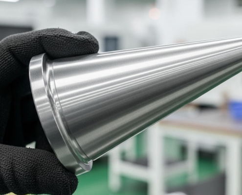
| Enhanced Surface Finish | Produces a superior surface quality with minimal tool marks or roughness. | Reduces the need for post-processing such as grinding or polishing, saving time and cost. |
| Improved Mechanical Performance | Creates parts with optimal load distribution and stress resistance. | Enhances fatigue life and overall durability of mechanical components. |
| Better Interchangeability | Achieves consistent and repeatable results across production batches. | Facilitates easy replacement and maintenance of precision components. |
| Material and Tool Efficiency | Optimizes cutting parameters and reduces unnecessary material removal. | Minimizes waste, extends tool life, and lowers production costs. |
| Versatility in Application | Applicable to various materials (steel, aluminum, titanium, etc.) and industries. | Supports diverse manufacturing sectors such as aerospace, automotive, and medical equipment. |
| Improved Process Control | Allows for integration with CNC systems and real-time monitoring. | Increases production stability, quality assurance, and automation capability. |
Even with modern machines, taper turning still brings some typical challenges. To get consistent and high-quality results, it’s important to pay attention to equipment condition, tool choice, and cutting methods.
Taper accuracy problems often come from poor machine stability, worn tools, or misalignment. Make sure the machine is firm and all parts are tightened properly. Check bearings and supports, and use steady rests for long workpieces. Keep cutting tools sharp and replace them when needed. Always check that the tailstock and centers are aligned correctly. For manual turning, try to keep the feed rate steady and follow a clear procedure. In CNC turning, check programs carefully and keep the machine well calibrated to avoid backlash or position errors.
A good surface finish depends on the right cutting speed, feed rate, and tool condition. If the feed rate is too high, the surface will be rough. If the speed is too low, the tool may rub instead of cutting. It’s usually better to take several light cuts instead of one heavy cut. Make sure the tool has the right shape and is sharp. A slightly larger tool nose radius can help create a smoother surface. Use enough cutting fluid to cool the workpiece and remove chips. Keep the setup firm to reduce vibration and get a cleaner finish.
Choosing the right tool is very important for taper turning. Pick the tool material according to the workpiece. Carbide tools are good for hard materials and high-speed work, while high-speed steel tools are fine for general use. A positive rake angle works well for softer materials, while a negative rake angle is better for harder materials. The nose radius also matters: a larger radius gives a better finish but can cause vibration if the setup is not stable. For internal tapers, make sure the tool has enough space to move without rubbing. Always keep the setup firm because a smaller, more rigid tool often gives better results than a larger one that might vibrate.
Taper turning is a highly useful machining process that plays an important role in many industries. It helps create parts that fit together accurately, move smoothly, and perform reliably. Below are some key examples of where taper turning is used.
| Industry | Typical Tapered Parts | Purpose / Function |
|---|---|---|
| Automotive | Tapered shafts in transmissions, propeller shafts, kingpins, ball joints | Ensure smooth movement, strong connections, and precise alignment for safe and reliable vehicle performance |
| Aerospace | Tapered pins, fasteners, turbine blade roots | Provide lightweight, strong connections and precise alignment; optimize aerodynamic performance and ensure flight safety |
| Machine Tool Manufacturing | Morse tapers, Jacobs tapers for spindles and tool holders | Self-centering and secure tool holding; reduce runout and improve machining accuracy |
| Medical Devices | Surgical instruments, prosthetic joints, dental implants | Enable secure attachments, smooth operation, and precise fit; meet high standards for surface finish and dimensional accuracy |
| Energy Sector | Drill pipe connections, valve seats, wind turbine shafts | Withstand high pressure, heavy loads, and harsh conditions; ensure reliable operation and structural integrity |
| Hydraulics and Pneumatics | Valve stems, poppets, sealing surfaces | Achieve leak-proof seals and controlled fluid flow; improve efficiency and reliability of fluid power systems |
From understanding taper to selecting the correct turning method, whether it’s tailstock positioning, compound toolholders, taper connections, or CNC turning with combined feeds, every step requires careful planning and precise operation. Accurate calculations and thorough setup are essential to avoiding errors, reducing waste, and improving production efficiency.
VMT’s team of precision machining experts can help you fully optimize your taper turning process. Leveraging extensive experience and advanced technology, VMT can transform complex production tasks with speed and precision, delivering higher quality and reliability for your products. Contact us today for a free CNC turning project consultation to make your production more efficient and competitive.
More Resources: What Is Taper?
What is the primary difference between taper turning and straight turning?
The primary difference lies in the resulting geometry of the workpiece. Straight turning creates a cylindrical shape where the diameter remains constant along the length. In contrast, taper turning produces a conical shape where the diameter changes uniformly from one end to the other, creating a specific angle relative to the lathe’s axis. This fundamental distinction defines their respective applications in manufacturing.
Which taper turning method is best for very long tapers with high precision?
For very long tapers requiring high precision, the taper turning attachment method on conventional lathes or, more ideally, the combining feeds method on a CNC turning center is generally preferred. The taper attachment keeps the workpiece aligned with the lathe axis, avoiding stress on centers, while CNC turning offers unparalleled accuracy and control over long lengths through synchronized axis movements.
What are the key benefits of using CNC machining for taper turning compared to conventional methods?
CNC machining offers significant benefits for taper turning. It provides superior precision and repeatability, virtually eliminating human error in setting angles and feeds. CNC turning allows for simultaneous control of multiple axes (combining feeds method), enabling the creation of complex tapers and excellent surface finishes with ease. It also reduces setup time, automates the process, and is highly efficient for high-volume production, leading to lower scrap rates and increased overall productivity compared to manual conventional methods.
What role does coolant play in achieving a good surface finish during taper turning?
Coolant plays a crucial role in optimizing surface finish during taper turning. It lubricates the cutting interface, reducing friction between the tool and workpiece, which prevents built-up edge formation and improves chip flow. More importantly, coolant dissipates heat generated during cutting, preventing thermal expansion of the workpiece and tool, which could lead to dimensional inaccuracies and poor finish. Proper coolant application also flushes away chips, preventing them from marring the surface.
When is the form tool method for taper turning most appropriate?
The form tool method is most appropriate for producing short tapers with relatively steep angles, especially in high-volume production scenarios. Its primary advantages are speed and simplicity, as it requires minimal setup. However, it is less suitable for long or shallow tapers due to higher cutting forces and potential for chatter, and it may not yield the best surface finish compared to other methods.


 Soft Machining: Methods, Materials, Advantages and Challenges in CNC Machin...