Engineering Drawing Symbols: A Comprehensive Guide
In engineering, engineering drawing symbols are more than just notations—they are the universal language that connects designers, engineers, and manufacturers. These symbols ensure that products are created with precision and efficiency, reducing errors in the design and production process, and ensuring all team members are aligned in their understanding of a project. This becomes especially crucial in CNC machining, where high precision and adherence to technical specifications are essential.
Engineering drawing symbols are essential tools used to communicate complex technical details about a component’s shape, size, material properties, and assembly. By simplifying and standardizing how information is conveyed, these symbols reduce miscommunication and are crucial for ensuring that designs meet specifications. This is particularly important in CNC manufacturing, where these symbols play a key role in guiding the production process.
Let’s dive deeper into the various types of engineering drawing symbols and their significance across multiple industries, particularly in the context of CNC machining, to help professionals create designs and components with greater accuracy and clarity.
What Are Engineering Drawings?
Engineering drawings are technical illustrations that convey the design, dimensions, and material specifications of a component or system. They are an essential part of the engineering process and are used to communicate exact details between teams. These drawings play an especially critical role in CNC machining, where precise measurements and tolerances are essential for ensuring the final product matches the design exactly.
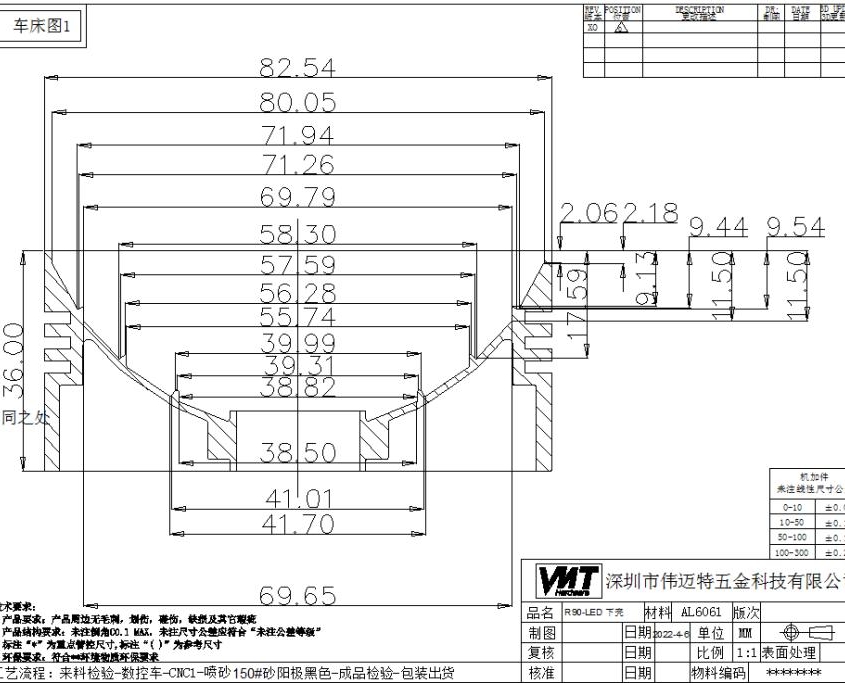
Engineering drawings act as detailed visual instructions, ensuring that the designer’s vision is executed exactly as planned. They are the primary communication tool between designers, manufacturers, and quality control engineers in CNC machining and other manufacturing fields.
Each drawing typically includes dimensions, tolerances, material types, and manufacturing processes, along with engineering drawing symbols that represent various mechanical, electrical, and physical attributes of the components. These drawings often guide CNC machining processes, including CNC milling, CNC turning, and drilling.
Note: If you want to learn more about engineering drawing, you can read the following article: Mechanical Engineering Drawing And Design: A Comprehensive Guide
What Are Engineering Drawings Used For?
Engineering drawings are vital for producing components that meet specific requirements, as they provide detailed visual representation of the design intent.
Designers use engineering drawings to visualize how a product will be constructed and how parts will fit together. Manufacturers use these drawings to create the product with high precision, ensuring all parts are fabricated according to specifications. CNC machining plays a significant role in this process, as it relies on these detailed drawings to create parts with extreme accuracy.
Engineering drawings are essential in industries such as automotive, aerospace, construction, and electronics. In CNC machining, for example, engineering symbols for drawings are used to indicate tool paths, material types, and the necessary finishes for components. In aerospace, for example, these symbols are critical for ensuring that parts meet the strict standards required for aircraft manufacturing.
What Are Engineering Drawing Symbols?
Engineering drawing symbols are graphical representations used in technical drawings to specify key features such as material type, dimension, tolerances, or machining processes. These symbols help standardize information so that everyone involved in the project can understand the design intent. For CNC machining, these symbols are crucial in guiding machine operators and engineers in producing the exact part as designed.
Instead of writing out lengthy descriptions for every part or feature, symbols in drawings provide a quick, standardized way of communicating essential data, saving time and reducing ambiguity. For CNC machining, engineering symbols for drawings guide every step of the process, from the initial design to final machining.
What Are the Symbols Used in Engineering Drawings?
Engineering drawing symbols are essential tools for conveying specific characteristics of parts and components. These symbols are designed to represent various features and properties, simplifying the complexity of the design and allowing engineers to communicate intricate details efficiently on a single drawing. In CNC machining, these symbols provide a standardized way to express dimensions, tolerances, surface finishes, and other essential information that directly influences the manufacturing process.
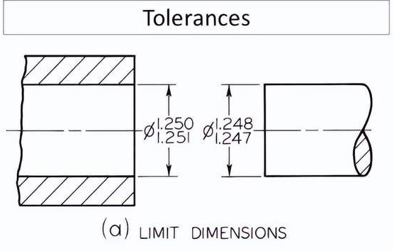
Geometric, Tolerance, and Surface Finish Symbols
These categories of symbols are pivotal in ensuring that the CNC machining process meets the design’s precision requirements.
1. Geometric Symbols: These symbols represent the shape or feature of a part. For example, the circle symbol might represent a hole or bore, while lines can indicate edges, centers, or axes. Geometric symbols like the diameter symbol (⌀) are used to specify the diameter of circular features on a part, while symbols for radius or fillet radius indicate the curvature of a part, which is crucial for operations like CNC milling.
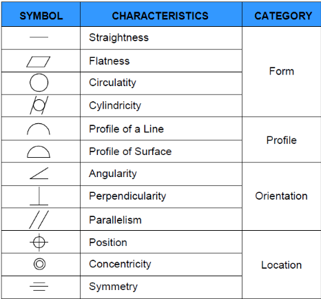
2. Tolerance Symbols: Tolerances specify the allowable limits of variation for a part’s dimensions. These symbols are essential in CNC machining, as they determine how closely a part must be manufactured to its designed dimensions. Geometric Dimensioning and Tolerancing (GD&T) symbols are often used, such as the flatness symbol, perpendicularity, and concentricity, which specify how precise the surfaces and features of the part should be. These symbols ensure that parts will fit together properly when assembled and meet performance requirements.
3. Surface Finish Symbols: These symbols indicate the required finish of the part’s surface after machining. In CNC machining, surface finish is critical to ensure proper function, aesthetics, and part longevity. Surface roughness symbols provide specific details about the type and roughness of the finish, such as Ra or Rt, which are vital for components that require smooth or textured surfaces.
Examples of Common Symbols on Engineering Drawings
Several key symbols are commonly used across various types of engineering drawings, particularly when preparing designs for CNC machining.
| Symbol Type | Description | Application in CNC Machining |
|---|---|---|
| Thread Symbols | Represents the type, size, and direction of threads for bolts, screws, and other fasteners | Ensures precise thread cutting and milling for accurate fit and functionality |
| Fillet Radius Symbols | Denotes the curved inside corners of a part to eliminate sharp edges | Enhances part strength, prevents stress concentration, and improves assembly ease |
| Hole Symbols | Specifies hole type, depth, and dimensions such as counterbore and countersink | Guides CNC drilling and milling for accurate hole placement and finishing |
| Welding Symbols | Indicates welding type, size, and process for joining parts | Helps in CNC machining preparation for welding, ensuring structural integrity |
| Bend Radius and Angle Symbols | Defines sheet metal bending curvature and angles | Ensures proper bending operations in CNC laser cutting and punching |
| Material Symbols | Specifies material type such as steel, aluminum, and plastic for manufacturing | Ensures correct material selection for required mechanical, thermal, and chemical properties |
| Countersink and Counterbore Symbols | Represents features designed to accommodate screw or bolt heads | Ensures accurate machining of conical or cylindrical features in drilling and milling operations |
Symbols in Specific Engineering Disciplines
In engineering, symbols are essential for clearly conveying the specifications of components, assemblies, and systems. These symbols are commonly used in mechanical and electrical engineering drawings and help guide CNC machining operations. Below, we explore the specific symbols used in mechanical and electrical engineering and their applications in CNC machining.
Symbols in Mechanical Engineering
In mechanical engineering, specific symbols are used to represent components such as fasteners, shafts, and other mechanical systems. These symbols in mechanical drawing are essential for guiding CNC machining operations, ensuring that each component is fabricated to the correct specifications.
Mechanical Drawing Symbols for Assemblies and Components: Mechanical engineers rely on mechanical drawing symbols to represent common parts like bolts, nuts, screws, and washers. Each of these symbols conveys detailed information about the size, material, and tolerance of the part, which is crucial when manufacturing these components with CNC machines.
Common Symbols in Mechanical Drafting: Some frequently encountered symbols in mechanical drafting include the bolt symbol, which represents the shape and size of bolts, and the weld symbol, which indicates the type of weld to be used, its size, and the weld’s location—critical information for CNC turning and CNC milling processes.
Symbols in Electrical Engineering
In electrical engineering, specialized symbols are used to design electrical circuits, control systems, and wiring diagrams. These symbols engineering play an important role in producing electrical components that must meet precise specifications, often required in CNC machining of electrical parts like connectors and casings.
Electrical Symbols for Circuits, Wiring, and Components: Symbols such as the resistor, capacitor, and diode are used to represent electrical components. These electrical engineering symbols help engineers visualize how components are connected in a circuit, ensuring that CNC machining operations for producing electrical components, like connectors and terminals, are executed accurately.
Electrical Engineering Drafting Standards: The symbols in electrical engineering must follow international standards like IEC 60617 or ANSI Y32.2 to ensure that all electrical components and wiring diagrams are universally understood. These standards also guide CNC machining of electrical parts, ensuring that they fit into larger systems precisely.
How to Read Engineering Drawings Symbols?
Reading engineering drawing symbols accurately is essential for interpreting a drawing correctly, particularly when translating these symbols into CNC machining instructions. For companies like VMT, which specialize in high-precision CNC machining services, understanding the meaning behind each symbol is crucial for achieving the desired product quality.
1. Learn Basic Shapes and Lines
Start with the basic shapes and lines used in engineering drawings. Once familiar, move on to more complex symbols like surface finishes, material types, and tolerances. Understanding these symbols is essential for creating CNC toolpaths and preparing for operations like CNC turning and milling. At VMT, we ensure that each drawing is carefully reviewed for accurate CNC processing.
2. Understand Symbol Placement and Context
The placement of symbols in a drawing is crucial. They indicate features like holes, slots, or fasteners and their positioning. At VMT, we emphasize understanding how symbols relate to the overall drawing to guide CNC machining accurately. This helps operators determine the correct sequence and settings for machining, ensuring the final product meets all specifications.

Why Use Abbreviations and Symbols in Engineering Drawings?
Abbreviations and symbols are critical for streamlining communication and reducing the size of drawings. CNC machining benefits greatly from these symbols, as they reduce the complexity of designs while ensuring that all necessary information is conveyed.
By using symbols like symbols in drafting for common features, engineers can avoid repetitive descriptions and focus on the essential information, saving space and time. For CNC machining, these symbols ensure that the machine operators and engineers understand the exact machining requirements.
Abbreviations and engineering symbols help to standardize communication between teams, ensuring that everyone understands the drawing without ambiguity. For instance, the TOL abbreviation denotes “tolerance,” which is crucial in defining the acceptable variation in part dimensions that is important for CNC machining accuracy.
Common Engineering Drawing Abbreviations
Abbreviations play a critical role in reducing clutter and streamlining the information presented in engineering drawings. By using abbreviations, engineers can convey a large amount of information in a compact and easily readable format. In CNC machining, these abbreviations are especially valuable for ensuring that all specifications are communicated clearly and without ambiguity. Proper use of abbreviations allows for a more efficient and effective manufacturing process, as it eliminates confusion and enhances precision.
Frequently Used Abbreviations in Engineering Drawings
Several abbreviations are commonly used in engineering drawings to represent essential details. Some of the most frequently used abbreviations include:
| Abbreviation | Description | Application in CNC Machining |
|---|---|---|
| DIM | Dimensions | Specifies the measurements of features such as length, width, height, diameter, and depth |
| TOL | Tolerance | Defines the allowable variation in a part’s dimensions for proper fit and function |
| ISO | International Organization for Standardization | Sets guidelines for technical specifications, including quality, dimensions, and tolerances |
| R | Radius | Indicates the size of a curved edge or feature, such as the radius of a corner or hole |
| Ø | Diameter | Denotes circular features such as holes or shafts |
| BOM | Bill of Materials | Lists all components, parts, and materials required for a project |
| C.S.K. | Countersunk | Specifies a hole with a conical opening at the top, often for seating a screw or bolt |
| C.Bore | Counterbore | Refers to a cylindrical hole with a flat bottom |
| T.B.D. | To Be Determined | Used when certain details like dimensions or materials are not finalized |
| L.D. | Lead | Refers to the lead of a thread in a threaded part |
Start Your CNC Machining Project with VMT
At VMT, we specialize in producing high-precision CNC-machined parts for a wide range of industries, including automotive, medical, industrial equipment, and electronics. With over 14 years of experience in CNC machining, we have honed our skills and techniques to consistently deliver top-tier results. Whether you’re looking to produce complex, intricate parts or high-volume production runs, VMT is your trusted partner in precision manufacturing.
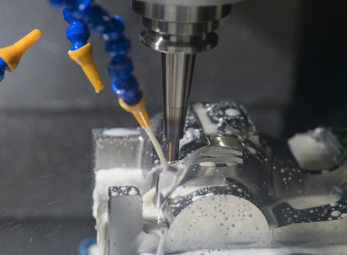
By utilizing the correct engineering drawing symbols and adhering to rigorous standards, we ensure that every part is fabricated to exact specifications. This attention to detail enables us to provide exceptional quality and consistency in CNC manufacturing. Our team of engineers, each with over 20 years of experience, works closely with clients to interpret engineering drawings, ensuring the highest accuracy and the best possible outcomes for each project.
Frequently Asked Questions About Engineering Drawing Symbols
How to Read Mechanical Engineering Drawing Symbols?
Mechanical engineering drawing symbols represent components, materials, and processes. To read them, start by understanding the key (legend) that defines each symbol. Familiarize yourself with standard symbols like lines (solid, dashed), shapes (circles, squares), and notations (diameters, angles). Additionally, pay attention to scale, dimensions, and tolerances to accurately interpret the drawing’s details.
What are the 4 Basic Components to Dimensioning?
The four basic components of dimensioning are:
Size dimension – indicates the size of an object.
Location dimension – specifies the position of features.
Angular dimension – shows the angle between features.
Tolerance – defines the allowable variation from the specified dimension, ensuring fit and function.
What are PFD Symbols?
PFD symbols (Process Flow Diagram) represent the major equipment and processes in a system. These symbols simplify complex processes, showing key elements like pumps, compressors, heat exchangers, and pipelines. They focus on the flow of materials and energy, often omitting intricate details for a broader understanding of the process layout.
How do Engineering Drawings, PFDs, and P&IDs Relate?
Engineering Drawings, PFDs, and P&IDs are all essential tools in process design and engineering. Engineering drawings detail individual parts and components, while PFDs show the overall flow of materials and energy in a system. P&IDs (Piping and Instrumentation Diagrams) provide a more detailed, specific look at the piping, instrumentation, and control systems in the process. All three tools work together to communicate design intent and system operation.


