Mechanical Engineering Drawing And Design: A Comprehensive Guide
Mechanical engineering drawings serve as the backbone for the creation of mechanical parts, ensuring that designs are executed with precision and clarity. Without well-prepared and accurate engineering drawings, manufacturing can become disorganized, leading to errors, delays, and increased costs. This comprehensive guide explores the essential aspects of engineering and drawing to help you create, understand, and utilize these critical documents in the mechanical engineering field.
Mechanical engineering drawings are essential to every stage of the product development lifecycle. From conceptualization to assembly, these drawings serve as blueprints that guide the creation of mechanical parts. This guide will walk you through how to make effective engineering drawings, understand the various components, and avoid common mistakes that can hinder the design and manufacturing process.
Let’s begin by understanding what mechanical engineering drawings are and how they facilitate the creation of detailed mechanical designs.
What are Mechanical Engineering Drawings?
Mechanical engineering drawings are graphical representations used to convey information about mechanical components or assemblies. These drawings provide detailed visual instructions on how a part should be constructed, assembled, and tested. They represent the shape, size, features, and relationships of the components that make up a product. These drawings are usually accompanied by notes or annotations to clarify details such as material specifications, dimensions, tolerances, and manufacturing processes.
In mechanical engineering, these drawings are often used for producing parts in industries such as automotive, aerospace, and machinery. Mechanical engineering drawings are essential for engineers to communicate ideas, and for manufacturers to translate those ideas into physical products.
How to Make Drawings?
Creating engineering drawings requires precision, planning, and knowledge of the design process. Whether hand-drawing or using CAD software, the steps to making an effective mechanical engineering drawing are as follows:
| Step | Description |
|---|---|
| 1. Conceptualization | Start by thinking through ideas and making rough sketches. This helps you choose the best design direction before you begin detailed work. |
| 2. Drafting | Turn your sketch into a real drawing using paper or CAD software like AutoCAD, SolidWorks, or CATIA. This step defines the basic shapes, parts, and sizes. |
| 3. Adding Details | Add important information such as exact measurements, materials, surface finishes, and tolerances. This makes the drawing ready for manufacturing. |
| 4. Review and Approval | Check the drawing for mistakes and make sure everything is clear. After review, make any needed changes and get final approval before production. |
The Basic Components of an Engineering Drawing
Every engineering drawing contains essential components that ensure the design is accurately communicated to manufacturers, engineers, and other stakeholders. These components are standardized to promote clarity, precision, and effective communication. Below is a detailed breakdown of the primary and supplementary components found in a typical engineering drawing:
1. Materials
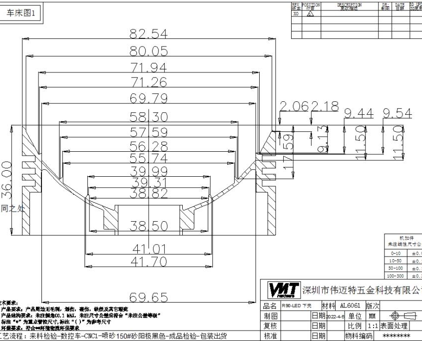
Specifying materials is one of the most critical aspects of any engineering drawing. Each component must indicate the material from which it is to be fabricated, such as steel, aluminum, plastic, or composites. Material specifications ensure that manufacturers select the correct raw materials, affecting the performance, durability, and cost of the final product.
Example: A part labeled as “Aluminum 6061” will differ significantly in properties and cost from one made of “Stainless Steel 316.”
Tip: Always include material grades, heat treatments, or coatings if applicable.
2. Geometry
Geometry defines the shape and structure of a part or assembly, represented through various drawing views:
Top View, Side View, Front View: These show the external contours and layout of the part.
Sectional Views: Used to display internal features that cannot be seen in standard views.
3D Isometric Views: Offer a realistic representation of the component for better visualization.
Geometry also includes features like angles, radii, curves, and symmetrical relationships, ensuring that the design intent is fully captured.
Tip: Ensure geometric tolerances are defined where critical.
3. Dimensions
Dimensions are the numerical values that indicate the size, location, and spacing of features on a component. Proper dimensioning ensures compatibility during manufacturing and assembly.
Key aspects of dimensions include:
Linear Dimensions: Indicate lengths, widths, and heights.
Angular Dimensions: Specify the degree of angles between features.
Diameter and Radius Dimensions: Used for holes, curves, and cylindrical features.
Tolerances: Define acceptable variations in size or position, ensuring the part functions as intended.

4. Title Block
The title block is a cornerstone of an engineering drawing, consolidating essential metadata for traceability and standardization. A comprehensive title block typically includes:
| Title Block Element | Description |
|---|---|
| Drawing Title and Number | The name and unique ID of the drawing. Helps people quickly identify and refer to the correct document. Often follows a company naming rule. |
| Material Specifications | Lists the exact material, including type, grade, and surface finish. Ensures the correct materials are used in manufacturing. |
| Drawing Scale and Units | Shows how the drawing size compares to the real object (e.g., 1:1 or 1:10). Also states if the measurements are in mm, inches, etc. |
| Revision History | A record of any changes made to the drawing. Includes details of what changed, who made the change, and the date. |
| Approval Information | Signatures or stamps of people who approve the drawing, such as engineers or managers. Confirms the drawing is ready for use. |
| Designer’s Name and Date | Shows who created the drawing and when it was made. Helps track responsibility and follow up if needed. |
5. Coordinates
Coordinates are a fundamental component in engineering drawings, ensuring precision and consistency in manufacturing processes. Key elements include:
Defining Locations: Exact positions of features like holes, slots, notches, and edges are specified using Cartesian or polar coordinate systems.
Datum Points and Reference Systems: Establish a baseline or reference for measurements, often using primary, secondary, and tertiary datums for comprehensive dimensional control.
Tolerance Zones: Coordinates are often paired with tolerances, specifying acceptable variations to maintain functionality. This is critical in applications requiring micrometer-level precision.
Consistency Across Operations: A unified coordinate system ensures alignment across multiple manufacturing stages, such as machining, inspection, and assembly.
Interoperability: Coordinates enable seamless integration with CNC machines, CAD software, and other digital tools, minimizing errors and ensuring repeatability.
Accurate coordinate usage prevents misalignments and ensures that parts fit together perfectly, maintaining the integrity of assemblies.
6. Types of Lines
Different line types convey unique information in an engineering drawing:
| Line Type | Purpose | Description |
|---|---|---|
| Continuous Line | Shows visible edges and outlines | Solid, unbroken lines that represent the outer shape, features, and dimensions of an object. These are the main lines used to draw the object itself. |
| Dashed Line | Shows hidden parts | Made of short dashes, these lines show edges or features that are not visible from the current view. They help reveal internal details without a cross-section. |
| Centerline | Marks centers and symmetry | Thin lines with alternating long and short dashes (or dots). Used to show the center of holes, axes of cylinders, and symmetry in a part. |
| Phantom Line | Shows alternate positions or motion | Lines made of long dashes and two short dashes. Used to indicate moving parts, alternate positions, or future modifications in a design. |
7. Notes and Annotations
Additional annotations often provide specific instructions, such as:
Surface Finishes: Specify the desired texture or roughness of surfaces, often using symbols that conform to ISO 1302 or equivalent standards. These affect both aesthetics and functionality.
Welding Instructions: Detail welding symbols, joint types, processes, and quality requirements, ensuring compatibility between materials and consistent strength.
Assembly Instructions: Provide guidelines for putting parts together, including torque values for fasteners, alignment steps, or lubrication points.
Inspection Standards: Define criteria for quality checks, such as tolerances, permissible defects, or compliance with industry standards (e.g., ISO, ASME, ASTM).
Special Handling or Storage Requirements: Include precautions for fragile, hazardous, or temperature-sensitive materials, preventing damage or safety hazards.
By following standardized practices and including all these components, engineers can minimize production errors, reduce costs, and streamline the manufacturing process.
Why Are Mechanical Engineering Drawings Useful?
Mechanical engineering drawings serve multiple purposes in the design and manufacturing processes, making them indispensable tools in the engineering field. Here’s why they’re so useful:
Communication: Engineering drawings allow engineers, manufacturers, and suppliers to share detailed and unambiguous information. They ensure that all stakeholders understand the design specifications clearly.
Precision: Through detailed views and precise dimensions, mechanical engineering drawings help manufacturers create components that meet the required tolerances and specifications.
Cost Efficiency: Clear and accurate engineering drawings reduce errors, rework, and material waste, ultimately saving time and money.
Legal Documentation: Detailed mechanical drawings can be used for legal purposes, such as patent applications, and they help maintain compliance with industry regulations and standards.
How to Prepare an Engineering Drawing?
Preparing an engineering drawing is a meticulous process that requires careful planning and adherence to industry standards. A well-prepared drawing ensures clear communication between designers, manufacturers, and other stakeholders. Below is to creating high-quality mechanical engineering drawings:
Conceptualization: Define the purpose and function of the part. Sketch the basic outline and identify all key features.
Drafting: Use a drawing board or CAD software to outline the basic geometry and structure of the part. Ensure the scale is set correctly.
Standardization: Follow industry-standard guidelines for line types, dimensions, and annotations.
Adding Annotations: After completing the layout, annotate the drawing with specific details such as material types, surface finishes, tolerances, and assembly instructions.
Review and Quality Check: Review the drawing for errors or omissions. Ensure all details are accurate and complete before finalizing the design.
Common Mistakes in Engineering Drawings
Even experienced engineers can make errors when creating mechanical engineering drawings. These mistakes can lead to inefficiencies, delays, and cost overruns. Here’s a breakdown of common mistakes and how to avoid them:
| Common Mistake | Why It’s a Problem | How to Avoid It |
|---|---|---|
| 1. Incorrect Dimensions | Parts may not fit properly, causing assembly errors and delays. | Use accurate measuring tools or CAD. Always review drawings before final approval. |
| 2. Missing Tolerances | Parts might be too tight or too loose, affecting function and durability. | Add tolerances for all key dimensions. Use GD&T where needed. |
| 3. Poor Readability | Confusing drawings can lead to manufacturing mistakes. | Keep layouts clean, use clear symbols, and follow standard drawing rules. |
| 4. Missing Views | Incomplete views may hide critical features, leading to wrong parts. | Always include necessary views—top, side, section, and isometric. |
| 5. No Material or Finish Specified | Using the wrong material or finish can cause product failure. | Clearly list material types and surface finishes in the drawing. |
| 6. Misaligned or Overlapping Features | Parts may be weak or hard to manufacture. | Use CAD tools to check alignment. Review designs carefully before release. |
| 7. Ignoring Industry Standards | Non-standard drawings confuse manufacturers and increase errors. | Follow standards like ASME Y14.5 or ISO 129 for symbols and formats. |
| 8. Overcomplicating the Design | Too much detail can make the drawing hard to understand. | Focus on important features. Use extra documents for non-essential info. |
| 9. Outdated Title Block | Using the wrong version causes costly manufacturing mistakes. | Always update the title block with the latest revision and date. |
Tips for Using Mechanical Engineering Drawings
Mechanical engineering drawings are invaluable tools in product design and manufacturing, but their effectiveness depends on proper use. Here are some detailed tips to help you fully utilize these technical documents:
1. Check the Title Block
The title block provides critical metadata about the drawing.
Key Information: Verify the drawing number, scale, material specifications, revision history, and drafter’s name.
Purpose and Context: Ensure the title block aligns with the intended use, such as prototyping, production, or documentation.
Version Control: Double-check that you’re working with the latest revision to avoid errors caused by outdated information.
2. Understand the Scale
The scale defines the proportional relationship between the drawing and the actual part.
Reading the Scale: Common scales include 1:1 for full-size drawings or 1:10 for larger components. Always confirm the scale before taking measurements or interpreting dimensions.
Impact on Accuracy: Misinterpreting the scale can lead to incorrect assumptions about part sizes and fit, potentially causing costly errors during production.
Annotations for Exceptions: Look for notes indicating which parts of the drawing deviate from the primary scale (e.g., enlarged details or reduced views).
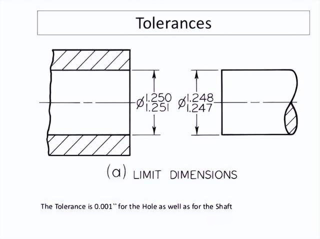
3. Read Tolerances Carefully
Tolerances dictate acceptable variations in dimensions, ensuring functionality and compatibility.
Key Details: Focus on the geometric tolerances (e.g., flatness, roundness) and dimensional tolerances (e.g., ±0.05 mm).
Functional Importance: Understand which tolerances are critical for assembly, performance, or safety. Pay extra attention to tight tolerances, as they can increase manufacturing complexity and costs.
GD&T Symbols: Familiarize yourself with Geometric Dimensioning and Tolerancing (GD&T) symbols, which convey complex tolerance requirements efficiently.
Note: If you want to learn more about tolerance, you can click to read the following article: CNC Machining Tolerance Guide: Definition & Types, Tolerance Press Fit: A Comprehensive Guide
4. Use CAD Tools
Modern CAD software greatly enhances the utility and accuracy of mechanical engineering drawings.
Editing Efficiency: CAD tools like AutoCAD, SolidWorks, and CATIA allow for quick modifications and real-time error checking.
Visualization: Use 3D modeling features to better understand part relationships, clearances, and assemblies.
Data Sharing: Export drawings in formats like DWG or STEP to ensure compatibility with other teams or software.
Automation: Leverage features like dimensioning automation, part libraries, and simulation tools to speed up the design process and reduce human error.
5. Follow Standard Drawing Practices
Adhering to standards ensures your drawings are universally understandable and technically accurate.
Industry Standards: Follow guidelines such as ASME Y14.5 or ISO 129 for dimensioning, tolerances, and symbols.
Consistency: Use uniform line types, fonts, and annotation styles across all drawings.
View Selection: Ensure that the chosen views (e.g., orthographic, isometric, or sectional) effectively convey the design intent.
Clear Annotations: Avoid clutter by keeping annotations concise and using callouts to reference additional details when needed.
6. Verify Assembly Fit and Function
Before finalizing the design, ensure that all parts in the drawing fit and function together as intended.
Cross-Check Dimensions: Compare dimensions across related parts to confirm compatibility.
Use Assembly Views: Rely on exploded or sectional views to visualize part relationships and identify potential interferences.
Simulations: Utilize CAD simulation tools to test mechanical performance under real-world conditions.
7. Train and Communicate with Teams
Mechanical engineering drawings are often shared among multidisciplinary teams.
Training: Provide training for team members unfamiliar with reading technical drawings or CAD software.
Communication: Use annotations, legends, and explanatory notes to bridge gaps in understanding, especially for complex designs.
Collaboration Tools: Leverage cloud-based CAD platforms for real-time collaboration and feedback.
Start Your Custom Machining Project Today
Are you starting a new project and unsure if your design drawings are ready for production? We’re here to help. At VMT, we work closely with you to review your drawings, give fast, practical feedback, and suggest improvements that make manufacturing easier and more efficient.
With 15 years of experience in CNC machining, our expert team checks every detail to ensure your parts are made right the first time. Contact us now for a free quote and get your project moving!
Frequently Asked Questions
How to Read Mechanical Drawings?
To read mechanical drawings, start by understanding the symbols and notations commonly used, such as dimension lines, tolerances, and material specifications. Familiarize yourself with orthographic projections, which show multiple views (top, side, front) of the object. Pay attention to scales and labels that indicate specific measurements and part features. Also, ensure you understand the section views and detail views, which provide more information on complex areas of the drawing.
What is a Drawing Area on a Blueprint?
The drawing area on a blueprint refers to the designated space where the actual illustrations of the parts, assemblies, or structures are drawn. This area is typically surrounded by a border and title block, which contains essential information like the drawing title, scale, date, revision details, and drawing number. The drawing area is where all the visual representation of the part or system is displayed, scaled to size.
Is Engineering Drafting and Design Important for CNC Machining?
Yes, engineering drafting and design is crucial for CNC machining because it provides the precise instructions needed to produce parts accurately. Well-drafted designs define dimensions, tolerances, and material types, which are essential for programming the CNC machine. It also helps in identifying potential manufacturing challenges, reducing errors, and ensuring that the final product meets the required specifications and quality standards. Without proper drafting, CNC machining would be inefficient and prone to mistakes.