Sheet Metal Prototyping: Precision Engineering Guide
Struggling with prototyping errors that delay production and increase costs? Our guide reveals precision engineering techniques to create flawless sheet metal prototypes efficiently.
Achieving high-precision sheet metal prototyping involves careful materials selection, advanced CNC machining, optimized design for manufacturability, and rigorous quality control. This guide provides actionable steps to reduce errors, improve surface finishes, and meet exact tolerances for rapid prototyping needs.
Read on to explore techniques, tools, and best practices for precise metal prototypes.
What is a Sheet Metal Prototype?
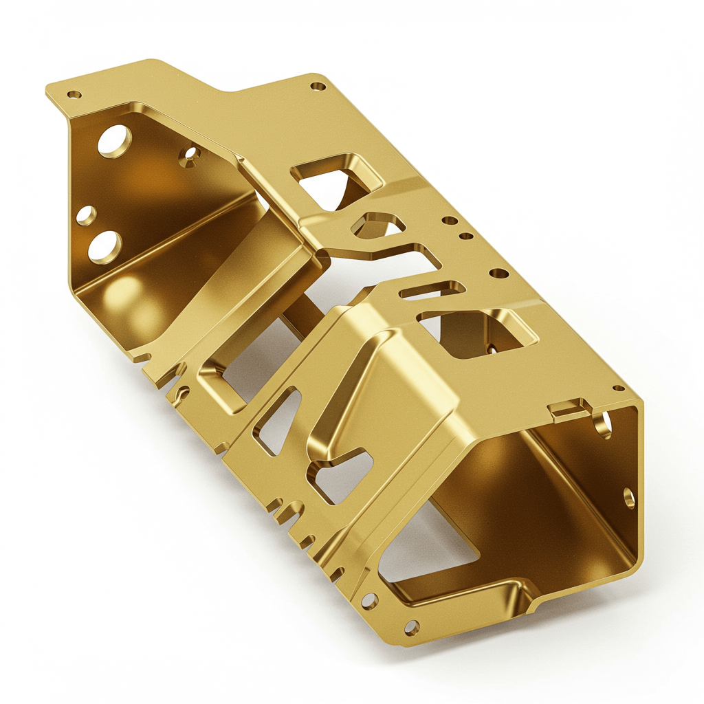
A sheet metal prototype is a physical representation of a product made from sheet metal to test form, fit, and function before full-scale production. Unlike plastic prototypes, sheet metal prototypes can endure higher stress, heat, and wear, offering realistic performance testing and structural validation. They are essential for verifying bends, folds, assemblies, and overall mechanical integrity of the final design.
VMT combines advanced CNC cutting, bending, and welding techniques to produce prototypes that accurately replicate the final product’s mechanical and structural characteristics, enabling efficient validation before mass manufacturing.
When Should You Use Metal for Prototyping?
Using metal for prototyping is ideal when your project requires high strength, durability, or precise tolerances. Metal prototypes are crucial in industries like automotive, aerospace, and electronics where functionality under stress or thermal conditions must be validated. Opting for metal CNC machining ensures the prototype mirrors the final production part’s performance, minimizing risks during mass production.
What Are the Common Sheet Metals Used in Rapid Prototyping?
Rapid prototyping often uses sheet metals with excellent machinability, durability, and the ability to withstand functional testing. Selecting the right sheet metal is crucial because it affects manufacturability, structural performance, and the accuracy of bends, folds, and assemblies. The following summarizes typical choices:
| Metal | Characteristics | Typical Applications |
|---|---|---|
| Aluminum | Lightweight, corrosion-resistant, excellent thermal conductivity, easy to cut, bend, and form | Electronics enclosures, automotive panels, aerospace components |
| Steel | High strength, durable, heat-resistant, available in multiple grades (e.g., stainless, carbon) | Industrial machinery, structural brackets, tooling components |
| Brass | Good corrosion resistance, easy CNC machining and forming, attractive finish, moderate strength | Valves, connectors, decorative panels, small mechanical parts |
| Copper | Excellent thermal and electrical conductivity, corrosion-resistant, easy to shape and bend | Electrical components, heat sinks, thermal management panels |
In addition to these common sheet metals, specialized applications may use titanium, nickel alloys, and magnesium for extreme strength, lightweight properties, or high-temperature and corrosion resistance.
Choosing the appropriate sheet metal ensures that prototypes replicate the mechanical, thermal, and electrical characteristics of the final product, facilitates early identification of design issues, and optimizes performance while minimizing costly revisions during mass production.
What Is the Process for Creating a Sheet Metal Prototype?
Creating a sheet metal prototype requires a structured workflow to ensure precision, functionality, and manufacturability. Each step transforms a concept into a tangible, testable part while accounting for bends, folds, and assemblies unique to sheet metal.
1. CAD Modeling
Engineers first create a detailed CAD design, simulating performance and identifying potential issues such as bend allowances, edge clearances, and assembly fit. Accurate modeling reduces errors during fabrication.
2. Material Selection
Choosing the right sheet metal is critical. Considerations include strength, thickness, machinability, corrosion resistance, and surface finish, all of which influence bending, forming, and overall performance.

3. CNC Cutting and Machining
Sheet metal is cut and machined using CNC laser cutting, waterjet cutting, or punching to achieve precise geometries. This step ensures accurate dimensions and preparation for bending or forming operations.
4. Bending and Forming
Using CNC press brakes or specialized forming tools, sheet metal is bent and shaped according to the design. Proper allowances for spring-back and bend radii ensure structural integrity and assembly accuracy.
5. Surface Treatment
After forming, surface finishing processes such as anodizing, powder coating, or plating improve durability, corrosion resistance, and visual quality, making the prototype ready for evaluation.
6. Quality Inspection
Dimensional checks, functional testing, and visual inspections verify that the prototype meets design specifications. Any deviations are corrected to maintain performance and assembly compatibility.
 7. Final Adjustments
The prototype undergoes final fine-tuning, ensuring it accurately represents the intended product and is ready for real-world testing or design validation before mass production.
CNC Machining vs Sheet Metal Fabrication
CNC machining and sheet metal fabrication are complementary approaches in creating precise metal prototypes. CNC machining involves removing material from solid metal blocks using milling, turning, and drilling operations, achieving tight tolerances and complex geometries.
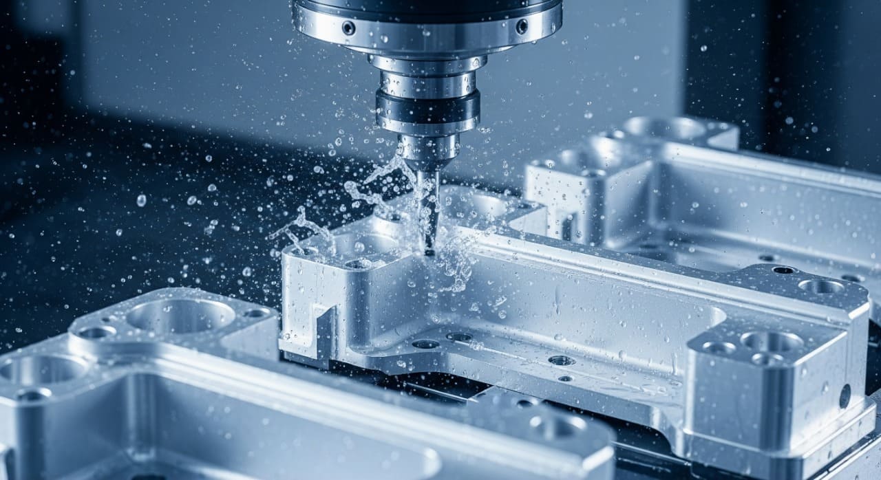
Sheet metal fabrication relies on bending, cutting, and stamping thin metal sheets, ideal for lightweight enclosures or structural panels. Choosing the right method depends on design complexity, material type, and functional requirements. Hybrid approaches often combine both techniques for optimal precision and efficiency.
Design Considerations for Sheet Metal Prototypes
Effective design for manufacturability ensures that your prototype can be produced accurately with minimal errors. Key considerations include bend radii, hole spacing, edge clearances, and allowance for material spring-back during bending.
| Design Consideration | Description | Impact on Prototype |
|---|---|---|
| Bend Radii | Minimum bend radius depends on material thickness and type; prevents cracking or deformation. | Ensures accurate folds and structural integrity. |
| Hole Spacing & Placement | Adequate spacing between holes and edges prevents tearing or distortion during punching or drilling. | Improves assembly fit and avoids weak points. |
| Edge Clearances | Maintain proper distance between edges and bends to allow tooling access and avoid collisions. | Reduces errors and ensures smooth bending or cutting. |
| Material Spring-Back | Metal naturally springs back after bending; must be accounted for in design and tool programming. | Achieves precise angles and consistent part dimensions. |
| Tolerances | Typical CNC sheet metal tolerances range from ±0.01 mm to ±0.1 mm depending on complexity. | Ensures the prototype functions correctly and aligns with mating components. |
| Forming & Tooling Constraints | Consider limitations of available CNC press brakes, laser cutters, or stamping tools. | Prevents unmanufacturable features and reduces rework. |
| Surface Finish & Coating | Account for anodizing, powder coating, or plating in design to prevent interference with assembly. | Provides final prototype aesthetics and protects against corrosion. |
| Simulation & Validation | Use CAD/CAE simulation to predict deformation, stress points, and assembly fit. | Optimizes design before production, reducing errors and material waste. |
| Design for Assembly | Design bends, tabs, and slots to facilitate easy assembly and minimize fasteners. | Improves prototype usability and tests real-world assembly feasibility. |
The Applications of Sheet Metal Prototypes
Sheet metal prototypes are widely used in automotive, aerospace, medical equipment, electronics, and industrial machinery. High-precision CNC machined parts validate designs, test assembly processes, and ensure functional performance.
VMT, with over 15 years of experience and advanced 4-axis and 5-axis CNC centers, provides customized prototyping solutions with reliable repeatability. Contact us today to get a free quote for your sheet metal prototype project and accelerate your product development.

In Conclusion
High-precision sheet metal prototyping combines smart design, material expertise, and advanced CNC machining to produce reliable, functional, and visually perfect prototypes across industries. By carefully considering bend radii, tolerances, material properties, and assembly requirements, manufacturers can create prototypes that accurately replicate final products.
Frequently Asked Questions About Sheet Metal Prototype
How to quickly make sheet metal mock-up prototype parts?
Use rapid fabrication techniques like CNC laser cutting, waterjet cutting, or punching for precise shapes, followed by CNC bending or press brake forming for folds and angles. For simple mock-ups, low-volume or thinner sheet metals can speed production.
Quick assembly with temporary fasteners allows functional testing without full finishing. Simulation software beforehand ensures correct dimensions and bend allowances, reducing errors and iterations.
When is it appropriate to use sheet metal prototypes?
Sheet metal prototypes are ideal when testing bends, folds, structural integrity, or assemblies before mass production. They are used to validate mechanical performance, fit, and form, check manufacturability, optimize designs, and identify potential issues.
Industries like automotive, aerospace, electronics, and industrial equipment use them when metal durability, heat resistance, or functional testing is required, providing realistic feedback before committing to costly production runs.